Abstract
Modular access towers are increasingly used in construction, industrial maintenance, rooftop servicing, and excavation applications where conventional scaffold stair systems may be limited by installation time, relocatability, available footprint, and project-specific fabrication requirements. This study develops and evaluates a configuration-aware structural verification framework for a multi-level aluminum access stair system assembled from repeatable welded and bolted modules. The objective is to determine whether modular stair-tower configurations can satisfy strength, stability, connection, and anchorage requirements under site-specific gravity and environmental loading while maintaining the flexibility required for repeated assembly and reconfiguration. The methodology combines three-dimensional finite-element analysis in SAP2000, code-based aluminum member checks, analytical utilization and reserve-factor calculations, and separate verification of bolts, welds, base anchors, and tie-off anchors. A primary Colorado installation was assessed for dead, live, snow, wind, and seismic actions using 6061-T6 aluminum members. A separate Florida installation was reviewed as an independent cross-project case under a higher basic wind speed of 168 mph. Controlled manufacturing drawings for standard and compact towers ranging from one to ten stair modules were also examined to evaluate the influence of module count, total height, structural mass, footprint, and tie-back spacing. All reported structural components satisfied the unity utilization criterion. The governing 3 in × 3 in × 0.25 in aluminum angle reached a utilization ratio of 0.941. The base-anchor and tie-off-anchor interaction ratios were 0.752 and 0.651, respectively. A two-bolt field connection provided 16.57 kips of shear capacity against a demand of 12.39 kips. The results show that structural adequacy depends not only on individual member strength but also on inter-module load-path continuity, anchorage, connection reliability, lateral-restraint spacing, and site-specific environmental actions. The proposed framework provides a transferable engineering basis for comparing configurable lightweight access structures and supports future parametric optimization and experimental validation.
Keywords
Modular Access System, Aluminum Stair Tower, Finite-Element Analysis, Structural Verification, Bolted Connections, Construction Safety, Design Optimization, Industrial Maintenance
1. Introduction
Industrial plants, construction sites, excavation works, and rooftop maintenance areas frequently require temporary or permanent vertical access at locations where fixed stairs are unavailable. The access system must support personnel loads, resist environmental actions, maintain stable geometry, and integrate with surrounding structures without creating excessive installation time or project-specific fabrication. Conventional scaffold stair towers can satisfy many access needs, but they often require large crews, repeated inspection, and complete disassembly when the access point changes. These limitations motivate modular alternatives that can be assembled off-site, lifted into position, relocated, and reconfigured as the project progresses
| [9] | Lacey, A. W., Chen, W., Hao, H., Bi, K. Review of bolted inter-module connections in modular steel buildings. Journal of Building Engineering. 2019, 23, 207-219.
https://doi.org/10.1016/j.jobe.2019.01.035 |
| [10] | Srisangeerthanan, S., Hashemi, M. J., Rajeev, P., Gad, E., Fernando, S. Review of performance requirements for inter-module connections in multi-story modular buildings. Journal of Building Engineering. 2020, 28, 101087.
https://doi.org/10.1016/j.jobe.2019.101087 |
| [11] | Chua, Y. S., Liew, J. Y. R., Pang, S. D. Modelling of connections and lateral behavior of high-rise modular steel buildings. Journal of Constructional Steel Research. 2020, 166, 105901.
https://doi.org/10.1016/j.jcsr.2019.105901 |
| [12] | Lacey, A. W., Chen, W., Hao, H., Bi, K. New interlocking inter-module connection for modular steel buildings. Engineering Structures. 2021, 247, 113114.
https://doi.org/10.1016/j.engstruct.2021.113114 |
| [13] | Nadeem, G., Safiee, N. A., Abu Bakar, N., Karim, I. A. Finite element analysis of a proposed self-locking joint for modular steel structures. Applied Sciences. 2021, 11(19), 9277.
https://doi.org/10.3390/app11199277 |
[9-13]
.
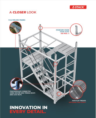
The Z-Stack concept uses repeatable aluminum stair modules connected vertically to form a multi-level tower. Standard and compact footprints are available, and access gates are positioned at recurring elevations to improve alignment with roofs, platforms, bridges, and excavation levels. The system combines fully welded subframes with field-bolted module interfaces, non-slip walking surfaces, guardrails, adjustable bases, crane-lifting provisions, and optional lateral ties consistent with applicable walking-working-surface safety requirements
. This architecture creates a product platform rather than a single project-specific stair structure
| [5] | SafeSmart Access. Z-Stack Engineered Aluminum Access Stair System Brochure. Santa Fe Springs, CA: SafeSmart Access; 2025. |
[5]
.
The principal engineering challenge is to preserve the benefits of modularity without introducing discontinuities in the structural load path. Repeated joints, lifting points, base supports, and tie-off interfaces may become critical even when individual frame members have adequate strength. In addition, a lightweight aluminum system is more sensitive to lateral displacement and overturning than a heavier steel structure. Consequently, member strength, connection reliability, anchorage, lateral restraint, and installation procedures must be evaluated as a single system.
Published research on modular structural systems consistently identifies inter-module connections as a governing link between local component behavior and global system response. Reviews of bolted modular connections show that connection stiffness, strength, constructability, and repeated assembly requirements must be considered together rather than treated as isolated detailing issues
| [9] | Lacey, A. W., Chen, W., Hao, H., Bi, K. Review of bolted inter-module connections in modular steel buildings. Journal of Building Engineering. 2019, 23, 207-219.
https://doi.org/10.1016/j.jobe.2019.01.035 |
| [10] | Srisangeerthanan, S., Hashemi, M. J., Rajeev, P., Gad, E., Fernando, S. Review of performance requirements for inter-module connections in multi-story modular buildings. Journal of Building Engineering. 2020, 28, 101087.
https://doi.org/10.1016/j.jobe.2019.101087 |
[9, 10]
. Numerical studies further demonstrate that the assumed rigidity of module interfaces materially affects lateral response and force redistribution in stacked systems
| [11] | Chua, Y. S., Liew, J. Y. R., Pang, S. D. Modelling of connections and lateral behavior of high-rise modular steel buildings. Journal of Constructional Steel Research. 2020, 166, 105901.
https://doi.org/10.1016/j.jcsr.2019.105901 |
[11]
. Experimental and numerical investigations of new modular joints commonly calibrate finite-element representations against component tests before conducting broader parametric studies
| [12] | Lacey, A. W., Chen, W., Hao, H., Bi, K. New interlocking inter-module connection for modular steel buildings. Engineering Structures. 2021, 247, 113114.
https://doi.org/10.1016/j.engstruct.2021.113114 |
| [13] | Nadeem, G., Safiee, N. A., Abu Bakar, N., Karim, I. A. Finite element analysis of a proposed self-locking joint for modular steel structures. Applied Sciences. 2021, 11(19), 9277.
https://doi.org/10.3390/app11199277 |
[12, 13]
. Although most prior work addresses building modules fabricated from steel, the same mechanics are relevant to lightweight aluminum access towers: repeated bolted interfaces, geometric discontinuities, lateral restraints, and erection constraints directly influence system stiffness and load-path continuity.
Research on lightweight prefabricated stair systems also indicates that transportation mass, deflection control, and structural capacity should be assessed simultaneously. Recent staircase studies have combined full-scale testing and finite-element analysis to quantify model error and demonstrate the value of independent validation
| [14] | Liu, J., Bao, Y., Qin, K. Experimental and Finite Element Analysis on the Structural Performance of Lightweight Hollow Slab Prefabricated Staircases. Buildings. 2025, 15(2), 245.
https://doi.org/10.3390/buildings15020245 |
[14]
. However, comparatively limited literature addresses reusable multi-level aluminum access towers that must function as configurable products across different heights, footprints, environmental hazards, tie-back arrangements, and access elevations. This gap motivates the present system-level methodology and its cross-project numerical verification.
This paper presents a system-level design and verification methodology for an evaluated multi-level configuration. The principal scientific contribution is a configuration-aware framework in which repeatable module geometry, global finite-element response, local member resistance, connection interaction, anchorage capacity, and height-to-base stability requirements are evaluated within one traceable workflow. Unlike a conventional project report that only establishes pass/fail compliance for a single structure, the present formulation defines reusable equations and decision metrics that can be applied to alternative module counts, footprints, access elevations, and environmental loading cases. The work integrates product architecture, manufacturing drawings, site-specific load definition, finite-element analysis, and component-level resistance checks to quantify structural efficiency and identify governing design constraints.
2. Materials and Methods
2.1. System Architecture and Configuration
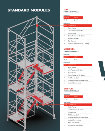
The access tower is assembled from bottom, intermediate, and top modules. The bottom module transfers load to adjustable bases or anchored supports, intermediate modules repeat the stair-and-landing geometry, and the top module completes the enclosure and provides the final access elevation. Standard modules have a nominal footprint of approximately 9 ft 4 in by 6 ft 10 in, while compact modules reduce the footprint to approximately 7 ft 7 in by 4 ft 11 in. Vertical connectors align the modules and provide locations for bolted attachment and lifting
| [15] | SafeSmart Access. 48-inch Tread Z-Stack Stair Module Manufacturing Drawing 15ZS-45S-48. Santa Fe Springs, CA: SafeSmart Access; 2025. |
| [16] | SafeSmart Access. 48-inch Tread Z-Stack Module Manufacturing Drawing ZS-MODULE-48. Santa Fe Springs, CA: SafeSmart Access; 2025. |
[15, 16]
.
The principal fabricated components include left and right-side frames, front and rear frames, stair flights, deck panels, handrails, brace members, connector posts, and base elements. The side frames use square tubes and angle sections arranged to support stairs, guardrails, and diagonal load paths. Manufacturing drawings define repeated section sizes and common connection details, allowing the same components to be used across multiple tower heights.
Figure 1. Representative modular stair unit showing welded frames, high-tensile bolted interfaces, non-slip treads, and crane hook slots.
Figure 2. Standard tower architecture assembled from top, intermediate, and bottom modules.
2.2. Material Properties and Design Basis
The primary superstructure was modeled using 6061-T6 wrought aluminum. This alloy was selected because of its strength-to-weight ratio, corrosion resistance, extrusion availability, and welding compatibility support rapid handling and outdoor service. The structural calculation package used a yield strength of 35 ksi, an ultimate tensile strength of 42 ksi, an elastic modulus of 10,000 ksi, and a unit weight of 0.284 lb/in3
| [5] | SafeSmart Access. Z-Stack Engineered Aluminum Access Stair System Brochure. Santa Fe Springs, CA: SafeSmart Access; 2025. |
[5]
.
Table 1. Material properties used in the structural verification.
Property | Value |
Aluminum alloy | 6061-T6 wrought |
Yield strength, fy | 35,000 psi |
Ultimate tensile strength, fu | 42,000 psi |
Elastic modulus, E | 1.0 x 10^7 psi |
Unit weight | 0.284 lb/in3 |
The evaluated project was in Arvada, Colorado. Design actions included dead, live, snow, wind, and seismic inputs. The calculation package referenced ASCE/SEI 7-22 for loading, ACI 318M-14 for concrete anchor checks, and the Aluminum Design Manual for member verification
| [1] | American Society of Civil Engineers. ASCE/SEI 7-22: Minimum Design Loads and Associated Criteria for Buildings and Other Structures. Reston, VA: American Society of Civil Engineers; 2022. https://doi.org/10.1061/9780784415788 |
| [2] | American Concrete Institute. ACI 318M-14: Building Code Requirements for Structural Concrete and Commentary. Farmington Hills, MI: American Concrete Institute; 2014. |
| [3] | The Aluminum Association. Aluminum Design Manual 2020. Arlington, VA: The Aluminum Association; 2020. |
| [6] | CEED Civil Engineering. Z-Stack ATI Construction Products Structural Calculation Report. Arvada, CO: CEED Civil Engineering; 2025. |
[1-3, 6]
. The model represented an open structure with wind exposure category C.
Table 2. Site-specific design parameters used for the evaluated configuration.
Design parameter | Reported value |
Dead load | 5 psf |
Live load | 50 psf |
Ground snow load | 55 psf |
Flat roof snow load | 39.4 psf |
Basic wind speed | 140 mph |
Wind exposure | Category C |
Seismic site class | D |
Spectral parameters | Ss = 0.20; SDS = 0.17; S1 = 0.045; SD1 = 0.068 |
2.3. Load Combinations and Structural Model
Allowable-stress and strength-design load combinations were considered. Representative combinations included D + L, D + S, D + 0.6W, 0.6D + 0.6W, 1.2D + 1.6L + 0.5S, 1.2D + 1.6S + 0.5W, and 0.9D + 1.0W. These combinations addressed gravity-dominant, snow-dominant, wind-dominant, and uplift or stability conditions. In these expressions, D denotes dead load, L live load, S snow load, and W wind load.
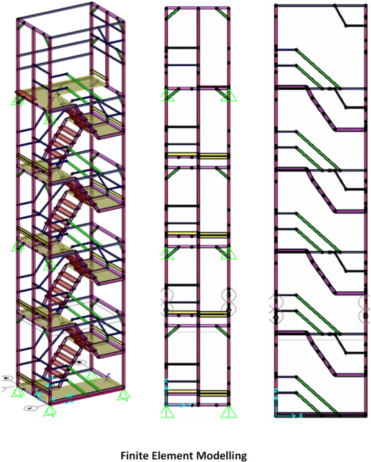
A three-dimensional finite-element model was developed in SAP2000. Frame elements represented posts, beams, braces, stair-support members, and selected handrail or connector members. Boundary conditions represented the evaluated base restraints and tie-off locations. Loads were applied to the structural framing, and member forces were extracted for individual capacity checks. The principal acceptance criterion was a demand-to-capacity utilization ratio not exceeding 1.0.
Figure 3. Three-dimensional finite-element model used to evaluate the stacked stair-tower configuration.
2.4. Analytical Formulation and Configuration Metrics
The structural assessment was expressed through a set of dimensionless performance measures so that different tower configurations can be compared on a common basis. For each member or connection, the governing utilization ratio U was defined as the ratio of factored or allowable demand Qd to the corresponding resistance Qr. A configuration satisfies the strength criterion when U ≤ 1.0. The reserve factor R provides a direct measure of remaining capacity and is defined as 1 − U.
For snow loading, the flat-roof snow pressure was calculated from the ASCE/SEI 7-22 relation using the exposure, thermal, and importance factors. The evaluated design used a ground snow load of 55 psf and produced a flat-roof snow pressure of 39.4 psf.
p_f = 0.7 C_e C_t I_s p_g(3)
Member axial stability was screened using the Euler elastic buckling relation, with the effective-length coefficient K selected to represent the idealized end restraint. Although final member resistance was obtained from the aluminum design checks, the elastic relation provides a transparent indicator of the sensitivity of slender posts and braces to changes in unsupported length
| [7] | Gere, J. M., Goodno, B. J. Mechanics of Materials. 9th ed. Boston, MA: Cengage Learning; 2018. |
| [8] | Hibbeler, R. C. Structural Analysis. 10th ed. New York, NY: Pearson; 2018. |
[7, 8]
.
2.5. Connection and Anchorage Verification
Connection checks were performed separately because modular structures can be governed by localized forces at module interfaces, lifting points, base supports, and external ties. The base-plate analysis considered a standard pipe support attached to a concrete foundation using heavy-hex anchors. A separate lateral connection check considered combined shear and pullout demand at the tie-off location. Bolted shear capacity was evaluated for a two-bolt field connection, and a representative welded attachment was checked using the effective throat of a fillet weld.
For lateral stability, the product configuration uses diagonal frame bracing and optional U-bolt tie-off brackets. Tie-off is required when the height-to-base ratio exceeds the applicable stability limit or when site-specific analysis indicates that lateral restraint is necessary. The location and spacing of ties must be determined from tower height, base width, wind exposure, adjacent structure capacity, and connection geometry.
For a bolted shear joint containing n bolts, the nominal group shear resistance was represented as the sum of the individual bolt resistances. The reported field connection was then assessed by comparing the applied shear Vd with the available group resistance Vr.
V_r = n φ V_b and U_v = V_d / V_r(5)
Anchor adequacy under combined tension and shear was evaluated with an interaction expression. The exponents α and β depend on the adopted design model; the conservative linear form shown below provides a transparent screening equation, while the final values reported in this study were obtained from the project anchor-design calculation.
(N_u / N_r) ^α+ (V_u / V_r) ^β≤ 1.0(6)
The representative fillet-weld resistance was calculated from the effective throat area. For weld leg size a, effective length Lw, and electrode tensile strength Fexx, the nominal weld strength is proportional to 0.707aLwFexx.
R_w = 0.707 a L_w F_exx(7)
2.6. Cross-Configuration Numerical Validation
Validation was performed at three complementary levels. First, the Colorado design package was checked through independent local calculations for member utilization, anchor interaction, bolt shear, and weld resistance. Second, SAP2000 results from a separate Florida installation were used as a cross-project case under different environmental inputs. Third, controlled manufacturing drawings for standard and compact towers were used to conduct a configuration study across increasing module counts. This approach is termed numerical and analytical validation because no measured full-scale displacement or strain data were available.
The Colorado case used a 140 mph basic wind speed, Exposure C, a 55 psf ground snow load, and Site Class D. The Florida case used a 168 mph basic wind speed, Exposure C, Site Class D, and the same nominal 50 psf live load
| [17] | CEED Civil Engineering. 766-Z-Stack Structural Calculation Report. Boca Raton, FL: CEED Civil Engineering; 2026. |
[17]
. The cases used the same general SAP2000-to-code-check workflow and aluminum material basis, but they were not identical structural models. Project-specific geometry, support and tie locations, connection details, boundary conditions, and environmental load inputs were modeled for each installation. Accordingly, the comparison demonstrates methodological repeatability rather than direct one-to-one structural equivalence.
Table 3. Cross-project numerical-validation matrix.
Parameter | Colorado case | Florida case |
Basic wind speed | 140 mph | 168 mph |
Wind exposure | C | C |
Site class | D | D |
Live load | 50 psf | 50 psf |
Primary alloy | 6061-T6 aluminum | 6061-T6 aluminum |
Analysis platform | SAP2000 | SAP2000 |
Verification scope | Members, anchors, bolts, welds | Members, reactions, wind response |
Table 4. Representative configuration data extracted from controlled manufacturing drawings.
Configuration | Total height | Platform height | Reported mass | Lateral-restraint note |
Compact 1-stack | 201.06 in | 103.34 in | 352.68 lb | Base-mounted |
Compact 2-stack | 298.69 in | 200.88 in | 592.07 lb | Base-mounted |
Compact 3-stack | 396.31 in | 298.59 in | 850.38 lb | Tie-backs introduced |
Compact 4-stack | 493.94 in | 396.13 in | 1,207.64 lb | Ties every two modules |
Compact 7-stack | 786.81 in | 689.00 in | 1,994.21 lb | Ties every two modules |
Standard 10-module tower | 96 ft 3 in overall | Multiple access elevations | 4,452.30 lb | Ties every three modules |
The configuration study treated module count n as the principal discrete variable. For a repeated module architecture, tower height and structural mass can be represented by H_n = H_0 + n h_m and M_n = M_0 + n M_m + M_t, where H_0 and M_0 describe the fixed base and cage contribution, h_m and M_m describe one stair-module increment, and M_t represents configuration-dependent ties and accessories. Compact-system drawings show an approximately constant vertical increment of 97.6 in per added stair module, while tie-backs are introduced at higher stack counts. Standard-system drawings likewise require periodic tie-backs, with the tall ten-module arrangement using ties every third stair module
| [18] | SafeSmart Access. Compact and Standard Multi-Stack Z-Stack Configuration Drawings. Santa Fe Springs, CA: SafeSmart Access; 2025-2026. |
[18]
.
3. Results
3.1. Aluminum Member Utilization
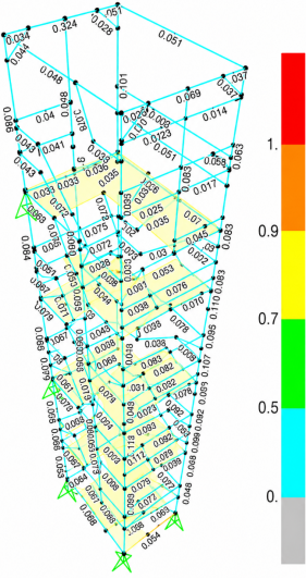
All summarized aluminum members satisfied the unity utilization criterion. The 3 in × 3 in × 0.25 in angle governed with Umax = 0.941 and therefore retained a reserve factor of R = 0.059. The 1.91 in outside-diameter round tube produced the second-highest utilization, U = 0.510, whereas the principal square-tube members remained between 0.081 and 0.257. The distribution of utilization indicates that the governing angle is efficiently engaged while several secondary members retain substantial capacity for configuration variability, local load redistribution, and fabrication tolerances.
Table 5. Maximum reported demand-to-capacity utilization ratios for principal aluminum members.
Member section and maximum utilization |
3 in x 3 in x 0.188 in square tube — U = 0.257 |
3 in x 3 in x 0.25 in angle — U = 0.941 (governing) |
1.5 in x 1.5 in x 0.25 in square tube — U = 0.081 |
2 in x 2 in x 0.25 in square tube — U = 0.081 |
1.5 in x 1.5 in x 0.188 in square tube — U = 0.082 |
1.91 in OD x 0.18 in wall round tube — U = 0.510 |
Figure 4. Model utilization output showing member demand-to-capacity ratios below the unity acceptance limit.
3.2. Connection Verification Results
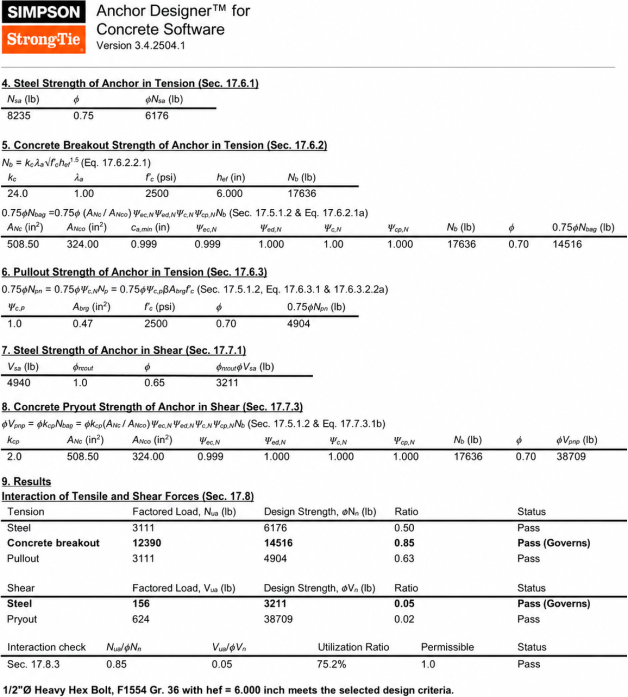
The base-anchor verification used a 1/2 in heavy-hex F1554 Grade 36 anchor with an effective embedment of 6.0 in. The reported combined interaction utilization was 0.752, giving a reserve factor of 0.248. The tie-off anchor was a 3/4 in mechanically galvanized Strong-Bolt 2 with 4.75 in nominal embedment; its reported interaction utilization was 0.651, corresponding to a reserve factor of 0.349. These margins are lower than those of most secondary aluminum members and confirm that anchorage and interface conditions must be included in configuration-level design decisions.
The field bolted shear connection used two 5/8 in ASTM A325 bolts. The available shear capacity was 16.57 kips against a demand of 12.39 kips, producing Uv = 0.748 and a capacity margin of 4.18 kips. The representative 1/4 in fillet-weld check over a 4 in effective length yielded a calculated resistance of 49.49 kips against a 0.59-kip demand. The large weld margin indicates that the evaluated local weld was not governing; however, fatigue, heat-affected-zone behavior, weld quality, and repeated assembly-induced load redistribution remain subjects for experimental verification.
Figure 5. Representative anchor interaction output used for base-connection verification.
Table 6. Summary of connection and anchorage verification.
Connection verification: demand and verified result |
Base anchor — 1/2 in F1554 Gr. 36; hef = 6.0 in; U = 0.752 |
Tie-off anchor — 4.56-kip shear; 0.59-kip pullout; U = 0.651 |
Bolted shear joint — 12.39-kip demand; 16.57-kip capacity |
Fillet weld — 0.59-kip demand; 49.49-kip resistance |
3.3. Modular Design Performance
The verified configuration demonstrates that a repeatable module can provide both structural continuity and field adaptability. The use of welded subframes limits geometric distortion within each module, while bolted interfaces permit transport, replacement, and reconfiguration. Aluminum construction reduces self-weight and supports manual assembly or crane relocation. Recurring access elevations and standardized accessories allow the tower to connect to roofs, bridges, work platforms, and excavation levels without redesigning the entire stair system.
3.4. Cross-Configuration and Cross-Project Results
The cross-project comparison confirmed that the same verification workflow could be applied to materially different site hazards. The Florida model was evaluated at a basic wind speed 20% higher than the Colorado case while retaining the same nominal live load and aluminum material basis
| [6] | CEED Civil Engineering. Z-Stack ATI Construction Products Structural Calculation Report. Arvada, CO: CEED Civil Engineering; 2025. |
| [17] | CEED Civil Engineering. 766-Z-Stack Structural Calculation Report. Boca Raton, FL: CEED Civil Engineering; 2026. |
[6, 17]
. However, the models were project-specific: geometry, restraints, connection details, boundary conditions, and load inputs were established for each installation. Both calculation packages reported member utilization below the unity limit, supporting transferability of the global-analysis/local-check workflow across regional loading conditions. This comparison is not a statistical validation dataset or an identical-model benchmark; it is an independent engineering case demonstrating methodological repeatability.
The configuration drawings showed nearly linear growth in height and mass with each repeated module, but lateral-restraint requirements changed discretely rather than continuously. The compact series introduces tie-backs for taller stacks and specifies ties for every two stair modules, whereas the tall standard series specifies ties for every three modules. Separate SAP2000 utilization plots for an untied four-stack configuration and a seven-stack configuration tied at the fourth stack further show that restraint layout must be treated as a design variable. The available plots support a qualitative comparison; exact improvement factors were not calculated because consistent nodal-displacement exports were not available for both models.
4. Discussion
The governing utilization ratio of 0.941 is significant from a modular-design perspective. A very low utilization ratio across all members would indicate unnecessary mass and reduced handling efficiency, while a ratio above unity would require redesigning. The governing angle section therefore represents a near-capacity component that should receive particular attention when geometry, load combinations, or connection details are changed. Because modular systems are reused in different configurations, a section that is acceptable in one tower height may not remain governing or adequate in another.
The results also show that connection design is inseparable from global system performance. The base anchor, tie-off anchor, and bolted shear connection all carried concentrated actions that were not represented by walking-surface load alone. Installation procedures, lifting arrangements, bridge attachments, and cantilever platforms can create load cases that differ from normal service conditions. For this reason, field accessories should be treated as structural components rather than optional convenience items.
Lateral stability remains the principal configuration-dependent issue. Increasing tower height increases overturning sensitivity, lateral displacement, and force demand at ties and base supports. Enclosures such as wire mesh can also increase wind area. A configuration used indoors or adjacent to a rigid structure may therefore require different restraints than a freestanding tower in an open exposure. Qualified engineering review is necessary whenever tower height, wind speed, snow loading, tie spacing, foundation geometry, or connected accessories differ from the evaluated case.
The finite-element and component-check workflow provides a reproducible verification method for configurable access products. Reusable member groups and standardized boundary-condition templates allow a new configuration to be generated from a limited set of parameters. Global analysis determines axial force, shear, moment, and displacement demand; local equations and code provisions then convert those demands into member, bolt, weld, and anchor utilization ratios. The separation of demand generation from resistance evaluation improves traceability, enables sensitivity studies, and reduces the risk that a locally adequate component is accepted without considering its role in the complete load path.
The expanded literature foundation clarifies the scientific position of the work. The equations used for utilization, buckling, anchor interaction, and weld resistance are established engineering relations; the novelty does not lie in redefining those mechanics. The contribution is the configuration-aware integration of these checks with controlled product geometry, cross-project environmental variation, and discrete tie-back rules. This is consistent with modular-structure literature, which emphasizes that global behavior depends strongly on connection assumptions and interface stiffness
| [9] | Lacey, A. W., Chen, W., Hao, H., Bi, K. Review of bolted inter-module connections in modular steel buildings. Journal of Building Engineering. 2019, 23, 207-219.
https://doi.org/10.1016/j.jobe.2019.01.035 |
| [10] | Srisangeerthanan, S., Hashemi, M. J., Rajeev, P., Gad, E., Fernando, S. Review of performance requirements for inter-module connections in multi-story modular buildings. Journal of Building Engineering. 2020, 28, 101087.
https://doi.org/10.1016/j.jobe.2019.101087 |
| [11] | Chua, Y. S., Liew, J. Y. R., Pang, S. D. Modelling of connections and lateral behavior of high-rise modular steel buildings. Journal of Constructional Steel Research. 2020, 166, 105901.
https://doi.org/10.1016/j.jcsr.2019.105901 |
| [12] | Lacey, A. W., Chen, W., Hao, H., Bi, K. New interlocking inter-module connection for modular steel buildings. Engineering Structures. 2021, 247, 113114.
https://doi.org/10.1016/j.engstruct.2021.113114 |
| [13] | Nadeem, G., Safiee, N. A., Abu Bakar, N., Karim, I. A. Finite element analysis of a proposed self-locking joint for modular steel structures. Applied Sciences. 2021, 11(19), 9277.
https://doi.org/10.3390/app11199277 |
[9-13]
. The present work extends that logic from volumetric building modules to reusable aluminum access towers and documents how height, mass, and restraint requirements evolve across a product family.
4.1. Scientific Novelty and Transferable Design Contribution
The novelty of this work is not the isolated use of aluminum, modular stairs, or finite-element analysis. It is the integration of these elements into a transferable configuration-verification framework. First, the module is treated as the fundamental design unit, permitting the effect of a local geometry or connection change to be propagated across manufacturing, transport, erection, and structural performance. Second, dimensionless utilization and reserve factors permit direct comparison of dissimilar members, anchors, and connections. Third, the approach explicitly separates global finite-element demand generation from local code-based resistance verification, producing an auditable chain from loading assumptions to governing components. This structure is suitable for future parametric automation and can support rapid screening of alternate tower heights, footprints, tie-off intervals, and access-gate locations before detailed project-specific engineering.
4.2. Limitations and Future Validation
The present study is limited to the supplied design documentation and reported numerical results. It does not include physical load testing, repeated assembly-cycle testing, fatigue evaluation of field-bolted interfaces, or dynamic lifting analysis. The supplied drawings and calculation packages do not specify a validated number of assembly-disassembly cycles for the bolted module interfaces. Therefore, no cycle-life claim is made. In practice, reusable connections require inspection for bolt or hole damage, thread condition, connection slip, corrosion, and permanent deformation before reassembly, with damaged components replaced in accordance with the manufacturer's procedures. A controlled cyclic assembly and proof-load program is recommended to establish connection stiffness retention, slip accumulation, and fatigue performance. The results are also specific to the evaluated site and boundary conditions, and additional simulations or tests are required before extending the conclusions to substantially different heights or loading environments.
5. Conclusions
A configuration-aware design methodology was developed for a modular multi-level aluminum access stair tower. The method combines repeatable module architecture, site-specific environmental actions, three-dimensional finite-element analysis, and component-level resistance equations within a single traceable verification process. The evaluated configuration satisfied all reported strength criteria, and the governing 3 in × 3 in × 0.25 in aluminum angle reached a utilization ratio of 0.941, demonstrating efficient material use while preserving a positive reserve to the unity limit.
Anchorage and connection behavior were shown to be essential system-level variables rather than secondary detailing considerations. The base-anchor and tie-off-anchor interaction ratios were 0.752 and 0.651, respectively, while the two-bolt field connection provided 16.57 kips of shear resistance against a 12.39-kip demand. The resulting utilization hierarchy identifies the governing member and interface conditions and provides a rational basis for configuration optimization.
Cross-project and cross-configuration verification strengthened the evidence base. The methodology was applied to Colorado and Florida cases with basic wind speeds of 140 and 168 mph, respectively, and to standard and compact towers spanning one to ten repeated modules. The results support methodological transferability, while also showing that tie-back spacing and boundary conditions become increasingly important with tower height. Because no physical displacement, strain, or proof-load measurements were available, these results are identified as analytical and numerical validation rather than experimental validation.
The proposed novelty is the transferable coupling of modular configuration variables with utilization, reserve, stability, and deployment requirements. The method can be extended to automated parametric studies that minimize mass and assembly effort while constraining maximum utilization and lateral displacement. The reported verification remains specific to the evaluated geometry, loading, supports, and anchorage assumptions; experimental load testing, repeated assembly-cycle testing, fatigue evaluation, crane-lift dynamic analysis, and validation of mesh-enclosure wind effects are recommended before broader generalization.
Abbreviations
ASCE | American Society of Civil Engineers |
ACI | American Concrete Institute |
FEA | Finite-Element Analysis |
OD | Outside Diameter |
OSHA | Occupational Safety and Health Administration |
SAP2000 | Structural Analysis Software |
IMC | Inter-Module Connection |
D | Dead Load |
L | Live Load |
S | Snow Load |
W | Wind Load |
Acknowledgments
The author acknowledges the product-development, drafting, manufacturing, and structural-engineering teams whose documentation supported this study. The manuscript is based on non-confidential technical information selected from product literature, engineering drawings, and a project structural calculation package.
Author Contributions
Nikhilkumar Patel: Conceptualization, Formal Analysis, Investigation, Methodology, Project administration, Resources, Visualization, Writing – original draft, Writing – review & editing
Data Availability Statement
The data supporting the outcome of this research work have been reported in this manuscript. The study uses controlled manufacturing drawings and project-specific engineering calculation packages for Colorado and Florida installations. Additional model files, detailed nodal outputs, and proprietary drawings may be available from the corresponding author subject to owner authorization, confidentiality restrictions, and third-party copyright limitations.
Conflicts of Interest
The author declares no conflicts of interest.
References
| [1] |
American Society of Civil Engineers. ASCE/SEI 7-22: Minimum Design Loads and Associated Criteria for Buildings and Other Structures. Reston, VA: American Society of Civil Engineers; 2022.
https://doi.org/10.1061/9780784415788
|
| [2] |
American Concrete Institute. ACI 318M-14: Building Code Requirements for Structural Concrete and Commentary. Farmington Hills, MI: American Concrete Institute; 2014.
|
| [3] |
The Aluminum Association. Aluminum Design Manual 2020. Arlington, VA: The Aluminum Association; 2020.
|
| [4] |
Occupational Safety and Health Administration. Walking-Working Surfaces, 29 CFR 1910 Subpart D. Available from:
https://www.osha.gov/laws-regs/regulations/standardnumber/1910/1910SubpartD
(accessed 28 July 2026).
|
| [5] |
SafeSmart Access. Z-Stack Engineered Aluminum Access Stair System Brochure. Santa Fe Springs, CA: SafeSmart Access; 2025.
|
| [6] |
CEED Civil Engineering. Z-Stack ATI Construction Products Structural Calculation Report. Arvada, CO: CEED Civil Engineering; 2025.
|
| [7] |
Gere, J. M., Goodno, B. J. Mechanics of Materials. 9th ed. Boston, MA: Cengage Learning; 2018.
|
| [8] |
Hibbeler, R. C. Structural Analysis. 10th ed. New York, NY: Pearson; 2018.
|
| [9] |
Lacey, A. W., Chen, W., Hao, H., Bi, K. Review of bolted inter-module connections in modular steel buildings. Journal of Building Engineering. 2019, 23, 207-219.
https://doi.org/10.1016/j.jobe.2019.01.035
|
| [10] |
Srisangeerthanan, S., Hashemi, M. J., Rajeev, P., Gad, E., Fernando, S. Review of performance requirements for inter-module connections in multi-story modular buildings. Journal of Building Engineering. 2020, 28, 101087.
https://doi.org/10.1016/j.jobe.2019.101087
|
| [11] |
Chua, Y. S., Liew, J. Y. R., Pang, S. D. Modelling of connections and lateral behavior of high-rise modular steel buildings. Journal of Constructional Steel Research. 2020, 166, 105901.
https://doi.org/10.1016/j.jcsr.2019.105901
|
| [12] |
Lacey, A. W., Chen, W., Hao, H., Bi, K. New interlocking inter-module connection for modular steel buildings. Engineering Structures. 2021, 247, 113114.
https://doi.org/10.1016/j.engstruct.2021.113114
|
| [13] |
Nadeem, G., Safiee, N. A., Abu Bakar, N., Karim, I. A. Finite element analysis of a proposed self-locking joint for modular steel structures. Applied Sciences. 2021, 11(19), 9277.
https://doi.org/10.3390/app11199277
|
| [14] |
Liu, J., Bao, Y., Qin, K. Experimental and Finite Element Analysis on the Structural Performance of Lightweight Hollow Slab Prefabricated Staircases. Buildings. 2025, 15(2), 245.
https://doi.org/10.3390/buildings15020245
|
| [15] |
SafeSmart Access. 48-inch Tread Z-Stack Stair Module Manufacturing Drawing 15ZS-45S-48. Santa Fe Springs, CA: SafeSmart Access; 2025.
|
| [16] |
SafeSmart Access. 48-inch Tread Z-Stack Module Manufacturing Drawing ZS-MODULE-48. Santa Fe Springs, CA: SafeSmart Access; 2025.
|
| [17] |
CEED Civil Engineering. 766-Z-Stack Structural Calculation Report. Boca Raton, FL: CEED Civil Engineering; 2026.
|
| [18] |
SafeSmart Access. Compact and Standard Multi-Stack Z-Stack Configuration Drawings. Santa Fe Springs, CA: SafeSmart Access; 2025-2026.
|
Cite This Article
-
APA Style
Patel, N. (2026). Design and Structural Verification of a Modular Multi-Level Aluminum Access Stair System for Maintenance and Construction Applications. American Journal of Mechanical and Industrial Engineering, 11(4), 81-92. https://doi.org/10.11648/j.ajmie.20261104.12
 Copy
|
Copy
|
 Download
ACS Style
Patel, N. Design and Structural Verification of a Modular Multi-Level Aluminum Access Stair System for Maintenance and Construction Applications. Am. J. Mech. Ind. Eng. 2026, 11(4), 81-92. doi: 10.11648/j.ajmie.20261104.12
Copy
|
Download
AMA Style
Patel N. Design and Structural Verification of a Modular Multi-Level Aluminum Access Stair System for Maintenance and Construction Applications. Am J Mech Ind Eng. 2026;11(4):81-92. doi: 10.11648/j.ajmie.20261104.12
Copy
|
Download
-
@article{10.11648/j.ajmie.20261104.12,
  author = {Nikhilkumar Patel},
  title = {Design and Structural Verification of a Modular Multi-Level Aluminum Access Stair System for Maintenance and Construction Applications},
  journal = {American Journal of Mechanical and Industrial Engineering},
  volume = {11},
  number = {4},
  pages = {81-92},
  doi = {10.11648/j.ajmie.20261104.12},
  url = {https://doi.org/10.11648/j.ajmie.20261104.12},
  eprint = {https://article.sciencepublishinggroup.com/pdf/10.11648.j.ajmie.20261104.12},
  abstract = {Modular access towers are increasingly used in construction, industrial maintenance, rooftop servicing, and excavation applications where conventional scaffold stair systems may be limited by installation time, relocatability, available footprint, and project-specific fabrication requirements. This study develops and evaluates a configuration-aware structural verification framework for a multi-level aluminum access stair system assembled from repeatable welded and bolted modules. The objective is to determine whether modular stair-tower configurations can satisfy strength, stability, connection, and anchorage requirements under site-specific gravity and environmental loading while maintaining the flexibility required for repeated assembly and reconfiguration. The methodology combines three-dimensional finite-element analysis in SAP2000, code-based aluminum member checks, analytical utilization and reserve-factor calculations, and separate verification of bolts, welds, base anchors, and tie-off anchors. A primary Colorado installation was assessed for dead, live, snow, wind, and seismic actions using 6061-T6 aluminum members. A separate Florida installation was reviewed as an independent cross-project case under a higher basic wind speed of 168 mph. Controlled manufacturing drawings for standard and compact towers ranging from one to ten stair modules were also examined to evaluate the influence of module count, total height, structural mass, footprint, and tie-back spacing. All reported structural components satisfied the unity utilization criterion. The governing 3 in × 3 in × 0.25 in aluminum angle reached a utilization ratio of 0.941. The base-anchor and tie-off-anchor interaction ratios were 0.752 and 0.651, respectively. A two-bolt field connection provided 16.57 kips of shear capacity against a demand of 12.39 kips. The results show that structural adequacy depends not only on individual member strength but also on inter-module load-path continuity, anchorage, connection reliability, lateral-restraint spacing, and site-specific environmental actions. The proposed framework provides a transferable engineering basis for comparing configurable lightweight access structures and supports future parametric optimization and experimental validation.},
 year = {2026}
}
Copy
|
Download
-
TY  - JOUR
T1  - Design and Structural Verification of a Modular Multi-Level Aluminum Access Stair System for Maintenance and Construction Applications
AU  - Nikhilkumar Patel
Y1  - 2026/08/20
PY  - 2026
N1  - https://doi.org/10.11648/j.ajmie.20261104.12
DO  - 10.11648/j.ajmie.20261104.12
T2  - American Journal of Mechanical and Industrial Engineering
JF  - American Journal of Mechanical and Industrial Engineering
JO  - American Journal of Mechanical and Industrial Engineering
SP  - 81
EP  - 92
PB  - Science Publishing Group
SN  - 2575-6060
UR  - https://doi.org/10.11648/j.ajmie.20261104.12
AB  - Modular access towers are increasingly used in construction, industrial maintenance, rooftop servicing, and excavation applications where conventional scaffold stair systems may be limited by installation time, relocatability, available footprint, and project-specific fabrication requirements. This study develops and evaluates a configuration-aware structural verification framework for a multi-level aluminum access stair system assembled from repeatable welded and bolted modules. The objective is to determine whether modular stair-tower configurations can satisfy strength, stability, connection, and anchorage requirements under site-specific gravity and environmental loading while maintaining the flexibility required for repeated assembly and reconfiguration. The methodology combines three-dimensional finite-element analysis in SAP2000, code-based aluminum member checks, analytical utilization and reserve-factor calculations, and separate verification of bolts, welds, base anchors, and tie-off anchors. A primary Colorado installation was assessed for dead, live, snow, wind, and seismic actions using 6061-T6 aluminum members. A separate Florida installation was reviewed as an independent cross-project case under a higher basic wind speed of 168 mph. Controlled manufacturing drawings for standard and compact towers ranging from one to ten stair modules were also examined to evaluate the influence of module count, total height, structural mass, footprint, and tie-back spacing. All reported structural components satisfied the unity utilization criterion. The governing 3 in × 3 in × 0.25 in aluminum angle reached a utilization ratio of 0.941. The base-anchor and tie-off-anchor interaction ratios were 0.752 and 0.651, respectively. A two-bolt field connection provided 16.57 kips of shear capacity against a demand of 12.39 kips. The results show that structural adequacy depends not only on individual member strength but also on inter-module load-path continuity, anchorage, connection reliability, lateral-restraint spacing, and site-specific environmental actions. The proposed framework provides a transferable engineering basis for comparing configurable lightweight access structures and supports future parametric optimization and experimental validation.
VL  - 11
IS  - 4
ER  -
Copy
|
Download






 Share This Article
 Twitter
 Linked In
 Facebook