The article discusses the study of the impact of the magnetic field (B) on the performance of a series vertical junction solar cell operating in static conditions and under polychromatic illumination. These solar cells consist of several non-monolithic junctions connected in series and illuminated from the edges. The theoretical approach is based on solving the continuity equation for excess minority charge carriers in the base (p-zone). This equation explicitly incorporates the influence of the magnetic field via the diffusion coefficient (D (B)), which is inversely proportional to 1+(μ. B) 2 (magnetoresistance phenomenon). The solution to the continuity equation is used to derive expressions for photocurrent (Jph), photovoltage (Vph), power (Pmax), form factor (FF), and conversion efficiency (η). The results clearly show that maximum power (Pmax) and conversion efficiency (η) decrease as the magnetic field increases (B). This effect is attributed to the Lorentz force, which deflects the trajectory of photogenerated carriers, significantly increasing their recombination rate before they reach the junction, thereby reducing the photocurrent. The study mainly shows that the optimum thickness (Hopt) of the base offering maximum power decreases as the magnetic field increases. This decrease is due to the fact that the magnetic field deflects the trajectory of minority carriers (electrons) towards the lateral faces of the cell. Therefore, for better carrier collection, the thickness of the base must be much thinner. The form factor (FF) is only very slightly affected by the magnetic field.
| Published in | American Journal of Modern Physics (Volume 15, Issue 1) |
| DOI | 10.11648/j.ajmp.20261501.11 |
| Page(s) | 1-8 |
| Creative Commons |
This is an Open Access article, distributed under the terms of the Creative Commons Attribution 4.0 International License (http://creativecommons.org/licenses/by/4.0/), which permits unrestricted use, distribution and reproduction in any medium or format, provided the original work is properly cited. |
| Copyright |
Copyright © The Author(s), 2026. Published by Science Publishing Group |
Magnetic Field, Solar Cell, Vertical Junction, Form Factor, Conversion Efficiency
Magnetic field B (10-4T) | 0 | 2 | 4 | 6 | 8 |
|---|---|---|---|---|---|
Optimum thickness Hopt (µm) | 345.12 | 333.18 | 303.71 | 268.20 | 234.48 |
Maximum power Pmax (10-2 W/cm2) | 2.84761 | 2.74970 | 2.50653 | 2.21241 | 1.93160 |
Magnetic field B (10-4 T) | 0 | 2 | 4 | 6 | 8 |
|---|---|---|---|---|---|
Optimum thickness Hopt (µm) | 345.12 | 333.18 | 303.71 | 268.20 | 234.48 |
Form Factor FF | 0.8113 | 0.8118 | 0.8116 | 0.8117 | 0.8103 |
Magnetic field B (10-4 T) | 0 | 2 | 4 | 6 | 8 |
|---|---|---|---|---|---|
Optimum thickness Hopt (µm) | 345.12 | 333.18 | 303.71 | 268.20 | 234.48 |
Conversion efficiency ƞ (%) | 28.4761 | 27.4970 | 25.0653 | 22.1241 | 19.3160 |
FF | Form Factor |
SCR | Space Charge Region |
BSF | Back Surface Field |
AM | Air Mass |
Isc | Short-Circuit Current |
Voc | Open Circuit Voltage |
| [1] | Betse, Y., Ritte, D., Bahir, G., Cohen, S. and Sperling, J. (1995). Measurement of the minority carrier mobility in the base of heterojunction bipolar transistors using a magnetotransport method”, Appl. Phys. Lett., Vol. 67, No. 13, Pp. 1883-1884. |
| [2] | Faye, D., Diop P., Dione B., and Ba M. Y. (2025). Influence of the Magnetic Field and Optimum Base Thickness of a Series Vertical-Junction Silicon Solar Cell under Polychromatic Illumination and Magnetic Field on Capacitance: Determination of Transition and Dark Capacitances. American Journal of Energy Research, vol. 13, no. 3: 80-85. |
| [3] | Diop, P., Samb, M. L., Faye, D., and Diop, M. M. (2024). Study In Transient Regime Of A Silicon Solar Cell: Influence Of Temperature And Magnetic Field. Journal of Fluid Flow, Heat and Mass Transfer (JFFHMT), 11. |
| [4] | Diop, G., Ba, H. Y., Thiam, N., Traore, Y., Dione, B., Ba, M. A., Diop, P., Diop, M. S., Mballo, O., and Sissoko, G. (1019). Base thickness optimization of a vertical series junction silicon solar cell under magnetic field by the concept of back surface recombination velocity of minority carrier. ARPN Journal of Engineering and Applied Sciences, Vol. 14, No. 23, pp. 4078 4085. |
| [5] | Faye, D., Gueye, S., Ndiaye, M., Ba, M. L., Diatta, I., Traore, Y., Diop, M. S., Diop, G., Diao, A., and Sissoko, G. (2020). Lamella silicon solar cell under both temperature and magnetic field: width optimum determination. |
| [6] | Diop M. S., Ba H. Y., Thiam N., Diatta I., Traore Y., Ba M. L., Sow E. H., Mballo O., and Sissoko G. (2019). Surface Recombination Concept as Applied to Determinate Silicon Solar Cell Base Optimum Thickness with Doping Level Effect. World Journal of Condensed Matter Physics, 9, 102-111. |
| [7] | Vardayan, R. R., Kerst, U., Wawer, P., Nell, M. N., and Wagemann, H. G (1998). Method of Measurement of All Recombination Parameters in the Base Region of Solar Cells. Proceedings of 2nd Conference and Exhibition on Photovoltaic Solar Energy Conversion, Vienna, 6-10 July 1998, 191-193. |
| [8] | Gover, A., and Stella, P. (1974). Vertical Multijunction Solar-Cell One-Dimensional Analysis. IEEE Transactions on Electron Devices, 21(5), 351–356. |
| [9] | Wise, J. F. (1970). Vertical junction hardened solar cell (U.S. Patent No. 3,690,953). U.S. Patent and Trademark Office. |
| [10] | Terheiden, B., Hahn, G., Fath, P., & Bucher, E. (2000). The Lamella Silicon Solar Cell. Dans Proceedings of the 16th European Photovoltaic Solar Energy Conference (pp. 1377–1380). WIP-Wirtschaft und Verlagsgesellschaft. |
| [11] | Hu, C., Carney, J. K., and Frank, R. I. (1977). New Analysis of a High Voltage Vertical Multijunction Solar Cell. Journal of Applied Physics, 48(2), 442–444. |
| [12] | Sarfaty, R., Cherkun, A., Pozner, R., Segev, G., Zeierman, E., Flitsanov, Y., Kribus, A., and Rosenwaks, Y. (2011). Vertical Junction Si Micro-Cells for Concentrating Photovoltaics. Dans Proceedings of the 26th European Photovoltaic Solar Energy Conference and Exhibition (pp. 145–147). |
| [13] | Furlan, J. and Amon, S. (1985). Approximation of the Carrier Generation Rate in Illuminated Silicon. Solid-State Electronics, 28, 1241-1243. |
| [14] | Sissoko, G., Sivoththanam, S., Rodot, M., and Mialhe, P. (1992). Constant Illumination-Induced Open Circuit Voltage Decay (CIOCVD) Method, as Applied to High Efficiency Si Solar Cells for Bulk and Back Surface Characterization. Dans Proceedings of the 11th European Photovoltaic Solar Energy Conference and Exhibition (pp. 352–354). |
| [15] | Sissoko, G., Museruka, C., Corréa, A., Gaye, I., and Ndiaye, A. L. (1996). Light Spectral Effect on Recombination Parameters of Silicon Solar Cell. Dans Proceedings of the World Renewable Energy Congress (Part III, pp. 1487–1490). Pergamon. |
| [16] | Joardar, K., Dondero, R. C., and Schroda, D. K. (1989). A Critical Analysis of the Small-Signal Voltage-Decay Technique for Minority-Carrier Lifetime Measurement in Solar Cells. Solid-State Electronics, 32(6), 479–483. |
| [17] | Fossum, J. G. (1977). Physical Operation of Back-Surface-Field Silicon Solar Cells. IEEE Transactions on Electron Devices, 24(4), 322–325. |
| [18] | Rose, B. H., and Weaver, H. T. (1983). Determination of Effective Surface Recombination Velocity and Minority-Carrier Lifetime in High-Efficiency Si Solar Cells. Journal of Applied Physics, 54(1), 238–247. |
| [19] | Diasse, O., Diao, A., Ly, I., Diouf, M. S., Diatta, I., Mane, R., Traore, Y., and Sissoko, G. (2018). Back Surface Recombination Velocity Modeling in White Biased Silicon Solar Cell under Steady State. Journal of Modern Physics, 9(2), 189–201. |
| [20] | Kaminski, A. (1997). Study of critical technological stages in the production of multicrystalline silicon solar cells [Doctoral thesis, National Institute of Applied Sciences of Lyon]. INSA Lyon. |
APA Style
Faye, D., Boiro, M., Dione, B., Diop, P. (2026). Optimization of Base Thickness in Response to Magnetic Fields: Towards a Robust Design for Vertical Solar Cells. American Journal of Modern Physics, 15(1), 1-8. https://doi.org/10.11648/j.ajmp.20261501.11
ACS Style
Faye, D.; Boiro, M.; Dione, B.; Diop, P. Optimization of Base Thickness in Response to Magnetic Fields: Towards a Robust Design for Vertical Solar Cells. Am. J. Mod. Phys. 2026, 15(1), 1-8. doi: 10.11648/j.ajmp.20261501.11
@article{10.11648/j.ajmp.20261501.11,
  author = {Dibor Faye and Mountaga Boiro and Babou Dione and Pape Diop},
  title = {Optimization of Base Thickness in Response to Magnetic Fields: Towards a Robust Design for Vertical Solar Cells},
  journal = {American Journal of Modern Physics},
  volume = {15},
  number = {1},
  pages = {1-8},
  doi = {10.11648/j.ajmp.20261501.11},
  url = {https://doi.org/10.11648/j.ajmp.20261501.11},
  eprint = {https://article.sciencepublishinggroup.com/pdf/10.11648.j.ajmp.20261501.11},
  abstract = {The article discusses the study of the impact of the magnetic field (B) on the performance of a series vertical junction solar cell operating in static conditions and under polychromatic illumination. These solar cells consist of several non-monolithic junctions connected in series and illuminated from the edges. The theoretical approach is based on solving the continuity equation for excess minority charge carriers in the base (p-zone). This equation explicitly incorporates the influence of the magnetic field via the diffusion coefficient (D (B)), which is inversely proportional to 1+(μ. B) 2 (magnetoresistance phenomenon). The solution to the continuity equation is used to derive expressions for photocurrent (Jph), photovoltage (Vph), power (Pmax), form factor (FF), and conversion efficiency (η). The results clearly show that maximum power (Pmax) and conversion efficiency (η) decrease as the magnetic field increases (B). This effect is attributed to the Lorentz force, which deflects the trajectory of photogenerated carriers, significantly increasing their recombination rate before they reach the junction, thereby reducing the photocurrent. The study mainly shows that the optimum thickness (Hopt) of the base offering maximum power decreases as the magnetic field increases. This decrease is due to the fact that the magnetic field deflects the trajectory of minority carriers (electrons) towards the lateral faces of the cell. Therefore, for better carrier collection, the thickness of the base must be much thinner. The form factor (FF) is only very slightly affected by the magnetic field.},
 year = {2026}
}
TY  - JOUR
T1  - Optimization of Base Thickness in Response to Magnetic Fields: Towards a Robust Design for Vertical Solar Cells
AU  - Dibor Faye
AU  - Mountaga Boiro
AU  - Babou Dione
AU  - Pape Diop
Y1  - 2026/01/16
PY  - 2026
N1  - https://doi.org/10.11648/j.ajmp.20261501.11
DO  - 10.11648/j.ajmp.20261501.11
T2  - American Journal of Modern Physics
JF  - American Journal of Modern Physics
JO  - American Journal of Modern Physics
SP  - 1
EP  - 8
PB  - Science Publishing Group
SN  - 2326-8891
UR  - https://doi.org/10.11648/j.ajmp.20261501.11
AB  - The article discusses the study of the impact of the magnetic field (B) on the performance of a series vertical junction solar cell operating in static conditions and under polychromatic illumination. These solar cells consist of several non-monolithic junctions connected in series and illuminated from the edges. The theoretical approach is based on solving the continuity equation for excess minority charge carriers in the base (p-zone). This equation explicitly incorporates the influence of the magnetic field via the diffusion coefficient (D (B)), which is inversely proportional to 1+(μ. B) 2 (magnetoresistance phenomenon). The solution to the continuity equation is used to derive expressions for photocurrent (Jph), photovoltage (Vph), power (Pmax), form factor (FF), and conversion efficiency (η). The results clearly show that maximum power (Pmax) and conversion efficiency (η) decrease as the magnetic field increases (B). This effect is attributed to the Lorentz force, which deflects the trajectory of photogenerated carriers, significantly increasing their recombination rate before they reach the junction, thereby reducing the photocurrent. The study mainly shows that the optimum thickness (Hopt) of the base offering maximum power decreases as the magnetic field increases. This decrease is due to the fact that the magnetic field deflects the trajectory of minority carriers (electrons) towards the lateral faces of the cell. Therefore, for better carrier collection, the thickness of the base must be much thinner. The form factor (FF) is only very slightly affected by the magnetic field.
VL  - 15
IS  - 1
ER  -
Department of Physics, Cheikh Anta Diop University, Dakar, Senegal
Department of Physics, Cheikh Anta Diop University, Dakar, Senegal
Department of Physics, Cheikh Anta Diop University, Dakar, Senegal
Department of Physics, Cheikh Anta Diop University, Dakar, Senegal
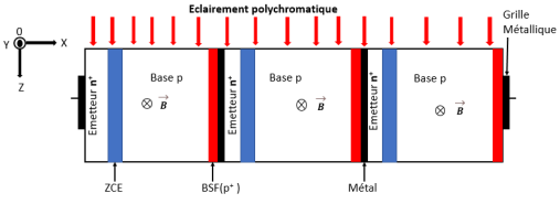
Figure 1. Diagram of a Solar Cell with Vertical Series Junctions Under Polychromatic Illumination and Under a Magnetic Field.
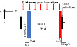
Figure 2. Structure of a Vertical Junction Silicon Solar Cell.
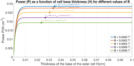
Figure 3. Shows the Variation in Power as a Function of the Thickness of the Solar Cell Base for Several Values of the Magnetic Field.
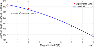
Figure 4. Profile of the Optimum Thickness Hopt as a Function of the Magnetic Field.
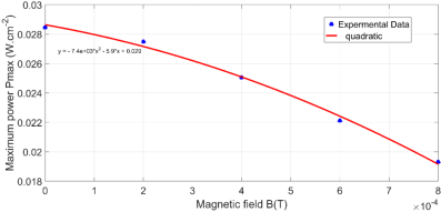
Figure 5. Maximum Power Evolution as a Function of the Magnetic Field.
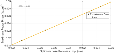
Figure 6. Evolution of Maximum Power Pmax as a Function of Optimum Thickness Hopt.
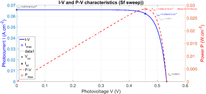
Figure 7. Photocurrent and Power Profiles as a Function of Photovoltage.
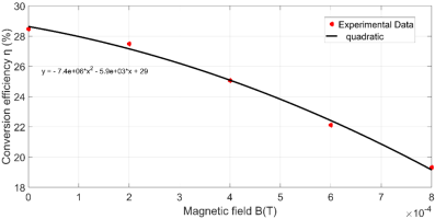
Figure 8. Evolution of Conversion Efficiency as a Function of Magnetic Field.
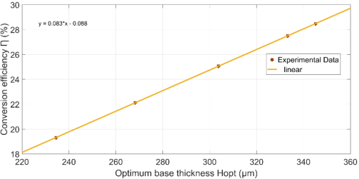
Figure 9. Variation in Conversion Efficiency as a Function of Optimum Thickness Hopt.
Information