Abstract
This study highlights the importance of radio as a major means of communication, particularly in French-speaking Africa. Despite the rise of digital media, radio remains widely used due to its accessibility, reliability, and ability to reach rural areas or regions with limited internet access. It also plays an important social and cultural role by fostering the exchange of information and community engagement. In the university setting, particularly at Gamal Abdel Nasser University in Conakry, the lack of an internal media outlet limits the dissemination of information. The creation of a university frequency modulation (FM) radio station is therefore proposed as a solution to improve internal communication, while also serving as an educational tool for students. We then described the technical design of a simple, low-cost FM transmitter capable of covering a distance of about 200 to 300 meters. We explained how it works, based on an oscillator, electronic components (transistors, capacitors, coils), and a microphone that converts sound into an electrical signal. Details are provided on construction, frequency tuning, and operating conditions. A discussion highlights certain technical limitations, such as interference, frequency instability, and range variability depending on the environment. Solutions are proposed to improve performance, including the use of appropriate antennas and amplifiers. Finally, we have emphasized that establishing a university radio station is technically feasible and beneficial. It serves as an effective tool for communication, learning, and promoting academic activities, while also contributing to the integration of communication technologies into higher education.
Keywords
Antenna, Coil, FM Radio, FM Transmitter, Low-Frequency, Microphone
1. Introduction
The world of communication is increasingly shifting toward digital platforms, offering vast opportunities for interaction. However, radio remains a leading medium of communication, particularly in French-speaking Africa. Indeed, it does not require extensive infrastructure, can be received even in the most remote areas, and—depending on the type of programming—allows for significant interaction with listeners.
Radio continues to hold a special place because it is perceived as one of the most reliable and credible media outlets. Studies show that in Africa, between 60% and 80% of the population listens to the radio regularly, making it the most inclusive and accessible medium, particularly in areas with low literacy rates and limited internet access.
Furthermore, radio plays a major social and cultural role: it connects communities, facilitates the flow of information, and promotes civic engagement
| [1] | Adane, I.B, Design and construction of an FM transmitter using phaselocked, Date: 2015,
https://ir.uew.edu.gh/handle/123456789/1544 |
| [2] | KM Awojobi, Kayode Martins; Olumuji, Emmanuel Olukunle; Atewolara-Odule, Odukunle Adebayo, RADIO LISTENERSHIP PATTERNS AND AFRICAN INDIGENOUS LANGUAGE PREFERENCES: A STUDY OF SELECTED YORUBA RADIO PROGRAMMES., Namibian Journal of Linguistics, Literature & Communication Studies, 2024, Vol 18, Issue 2, p 120. |
[1, 2]
. It thus remains a universal communication tool, capable of reaching both urban and rural areas. In French-speaking Africa, radio is not only a channel for information but also a space for dialogue and trust, which explains its continued dominance as a media platform despite the rise of digital platforms
| [3] | Muhammad A. Imran; Marco Zennaro; Olaoluwa R. Popoola; Luca Chiaraviglio; Hongwei Zhang; Pietro Manzoni, Exploring the Boundaries of Connected Systems: Communications for Hard-to-Reach Areas and Extreme Conditions, July 2024, Proceedings of the IEEE, 912 – 945,
https://doi.org/10.1109/JPROC.2024.3402265 |
[3]
.
Communication also plays a vital role in university life
| [4] | Olarewaju Peter Ayeoribe, Olaitan Akinsanmi and Ayodele S. Oluwole, Design and Construction of a Low-Power Frequency Modulation (FM) Transmitter for the Training Radio, (2025), Engineering engrxiv archive, pp.1-64,
https://doi.org/10.31224/5544 |
| [5] | Peters A O, Broadcasting Presentation on the Design and Construction of a 50 W Frequency Modulation Transmitter for the Training Radio at the Federal University Oye Ekiti, Ikole Campus, (2025), https://hal.science/hal-05163439v1 |
[4, 5]
. However, the lack of internal media outlets limits opportunities for sharing knowledge and information. Setting up an FM radio station would not only address this shortcoming but also serve as an educational resource for technical and communication programs.
Radio is also one of the most reliable sources of information, a factor that is particularly important in an era of misinformation and fake news. It also has the advantage of being able to broadcast under any circumstances, including during emergencies, wars, or other conflicts. Technically speaking, radio involves the transmission of signals via electromagnetic waves
| [6] | JP. C. Mbagwu, F.M.Ezike, J.O.Ozuomba, Design, Construction and Testing of a Low Energy Digital Frequency Modulation (FM) Transmitter, International Journal of Scientific & Engineering Research Volume 11, Issue 1, January-2020, pp 534-539, http://www.ijser.org |
| [7] | M. I. Efunbote, T. I. Ibrahim, J. O. Otulana, R. A. Jokojeje, DESIGN AND CONSTRUCTION OF FM TRANSMITER WITH THE RANGE OF 1.5 KM, International Journal of Recent Research in Electrical and Electronics Engineering (IJRREEE) Vol. 5, Issue 3, Month: July - September 2018, pp: 1-5, Available at: www.paperpublications.org |
[6, 7]
.
The main objective of this project is to develop a functional FM radio station tailored to the university’s needs, taking into account technical and regulatory constraints. The focus is on the challenges associated with the design, implementation, and optimization of the broadcast signal
. At Gamal Abdel Nasser University in Conakry (UGANC), information is currently disseminated via email, memos, phone calls, or meetings. Establishing a radio station within the institution could improve and facilitate internal communication, while enhancing the visibility of academic and scientific activities.
2. Tools and Methods
2.1. Electronic Diagram of an FM Transmitter
There are several electronic circuit diagrams for FM transmitters
| [9] | Deborsi Basu and Abhishek Bhowmik, Design and Implementation of a Smart & Portable Wireless FM Transmitter for Wide Range Communication, Journal of Engineering Research and Reports, August 2020, 15(2): 28-42,
https://doi.org/10.9734/JERR/2020/v15i217142 |
[9]
. At the UGANC laboratory, we have already built several different types. The one described below operates on a 9V DC power supply for about two hours continuously, but with an AC power source from the mains, it could operate continuously. It produces satisfactory results, with a range of approximately 200 to 300 meters in radius, depending on the transmission area conditions and the presence or absence of obstacles.
Its main advantage lies in its reliability and simplicity. What’s more, all the components are readily available and very inexpensive, which should be enough to convince a beginner to give it a try.
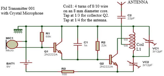
Figure 1. FM transmitter with a crystal oscillator.
2.2. How the FM Transmitter Works
The oscillator is built using a transistor (Q2) connected in an oscillating circuit consisting of an inductor (coil L1) and variable capacitors (VC1 and VC2). The variable capacitor VC1, connected in parallel with the coil L1, forms the resonant circuit that determines the transmission frequency. There are two ways to change this transmission frequency: either by varying the value of the variable capacitor VC1, or by slightly loosening or tightening the turns of coil L1. The variable capacitor VC2 allows you to adjust the feedback ratio and ensure reliable startup of the oscillation each time power is applied (it is well known that an amplifier that should not oscillate sometimes does, and that an oscillator that should oscillate does not always start). Sometimes this variable capacitor is replaced with a fixed 6.8pF or 8.2pF capacitor, and it still works.
The transistor is biased by the emitter resistor R3 (100 ohms, 5W) and the base resistor R2 (22 kOhms, 5W).
2.3. Coil L1
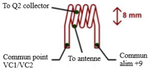
The L1 inductor (coil) must be made using 8/10 wire, where “8/10” refers to the wire's diameter in millimeters. Therefore, you should use wire with a diameter of 0.8 mm. Wind it around the barrel of a large felt-tip pen to create four or five turns with a diameter of about 8 mm, with each turn spaced about 2 mm to 3 mm apart from the next. Then, starting from the end that will be connected to the two variable capacitors VC1 and VC2 (at the bottom of the diagram), count one turn and strip the insulation from the copper wire so you can solder a small wire there to serve as an intermediate tap, which will be connected to the antenna via C2 (1/4 tap). One-third of a turn later, do the same so you can solder a small wire at this point to serve as an intermediate tap for the collector of transistor Q2 (1/3 tap). By proceeding in this way, you should end up with something that looks like the following diagram:
Figure 2. Collector of transistor Q2 (taken at 1/3).
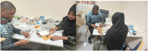
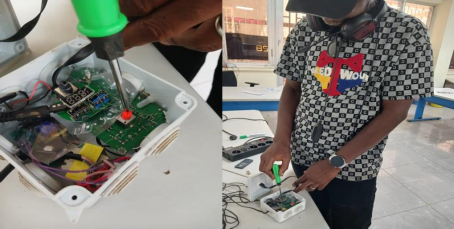
Below is a small example of a project built on a breadboard.
Figure 3. Soldering components to the perforated epoxy board.
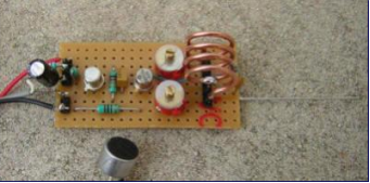
Figure 4. Chip-based experimental board, 87.5 MHz.
This prototype is tuned to 87.5 MHz by adjusting the two variable capacitors. Note the use of a miniature electret microphone instead of a crystal microphone.
2.4. Low-Frequency Circuit
Frequency modulation is achieved by varying the bias of the transistor (Q2) configured as an oscillator. This is accomplished by Q1, whose collector-emitter resistance varies in response to the signal applied between its base and collector, a signal derived from a “crystal” microphone. The DC bias of the base of transistor Q1 is provided by the 68K, 10W resistor R1.
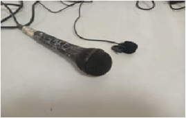
2.5. Microphone
A microphone (often shortened to “mic”) is an electroacoustic transducer, that is, a device capable of converting an acoustic signal into an electrical signal.
A diaphragm vibrates in response to sound pressure, and a device specific to the microphone’s technology converts these vibrations into electrical signals. A microphone’s design includes both an acoustic component and an electrical component, which determine its characteristics and intended use.
Figure 5. Crystal Microphones.
Using a dynamic microphone, which has a much lower output impedance, would require a slightly more complex input stage. The second reason is that crystal microphones are still available, they are inexpensive, they are lightweight, and they are perfectly suited for this kind of experiment. One piece of advice, however: keep the microphone cable as short as possible, because the longer the cable, the more noticeable the unwanted effects of frequency drift become when you move it...
When using a 3-wire electret microphone, you can simply add a capacitor and a resistor as shown in the following diagram, which uses an electret capsule.
Since the positive terminal of the power supply is grounded, you may naturally encounter some difficulty matching the wires of the electret microphone to the FM transmitter.
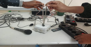
We have built two practical models, some images of which are shown in the figures below.
Figure 6. Frequency adjustment.
2.6. Settings
After carefully checking the wiring, we can proceed with the setup. To do this, we stand next to the radio receiver (preferably turned on) and turn on our transmitter. If we hear a small “pop” in the receiver at this point, that’s a good sign (but if we don’t hear anything, it doesn’t mean it isn’t working). Set the variable capacitors VC1 and VC2 to their midpoint (halfway between the two positions). Tune the FM receiver to the very bottom of the FM band (88 MHz)
| [10] | Wang, S. F., Li, D. W., Dong, H. S., Tian, R. L. (2022) Instantaneous frequency estimation of a nonlinear FM radar signal based on a multiscale chirplet path. Journal of Nanoelectronics and Optoelectronics, 17(2), 285-297.
https://doi.org/10.1166/jno.2022.3196 |
| [11] | Prince Chigozie Iwuji and Chibuzo Emeruwa, Investigation of Signal Strength-Level Generated by Orient 94.4 FM Transmitter in Imo State, Nigeria, International Journal of Science and Research (IJSR), Volume 7 Issue 5, May 2018, 1089-1094. https://doi.org/10.21275/ART20182892 |
| [12] | Akinbolati, A., Akinsanmi, O., and Ekundayo, K.R. (2016). Signal strength variation and propagation profiles of UHF radio wave channel in ondo state, Nigeria. International Journal of Wireless and Microwave Technologies. 6, 12-28.
https://doi.org/10.5815/ijwmt.2016.04.02 |
[10-12]
and speak into the microphone or tap it lightly while scanning up the FM band. At some point, you’ll hit the transmission frequency. If you scan the entire FM band without success, repeat the process after extending all the slats on the variable capacitor VC1.
If the FM band scan was unsuccessful again, repeat the procedure after adjusting all the slits on the variable capacitor VC1. If that still doesn’t work (you’re really out of luck here), loosen the windings on coil L1 slightly and try scanning the FM band again. If there’s still no signal, tighten the turns of coil L1 a little, and voilà—let’s try again! If you still haven’t heard anything after all that, that’s not a good sign; you’ll need to double-check all the wiring.
2.7. The Scope
In line of sight, with no obstacles, and using a highly sensitive receiver... As with any transmitter/receiver system, the range depends on the transmission power, the quality and sensitivity of the receiver, the antennas, and any obstacles between them. You can easily achieve a range of 300 meters in open terrain, but only 10 meters in an apartment with shielded walls.
To improve signal range, we used signal amplifiers in combination with dipole antennas mounted on a tall mast.
To ensure extensive coverage across a city or region, relay stations are used, consisting of amplifiers and antennas, along with power supplies tailored to the equipment’s requirements.
2.8. Antenna Length
The length of the antenna has a significant impact on the performance of the setup
| [13] | Gulnaz Yermoldina, Zharas Ainakulov, Zhanna Suimenbayeva, Andrey Bebenin, ANALYSIS OF WORLD EXPERIENCE AND EXPERIMENTAL IMPLEMENTATION OF UNMANNED RADIO INTELLIGENCE SYSTEMS, Transport and Telecommunication,, 2026, volume 27, no. 1, 73-92,
https://doi.org/10.2478/ttj-2026-0007 |
| [14] | Ajewole, M.O., Oyedum, O. D., Adediji, A. T., Eichie, J. O., Moses, A.S. Spatial Coverage of FM Radio Transmitters in Niger State, Nigeria, IUP Journal of Telecommunications, Vol. iv, No4, #70j-2012-11-01-01, pp 7-12, (2012). |
| [15] | Patrick, L. R. (2002). Radio Frequency propagation differences through various transmissive materials. Unpublished Master of Science thesis, University of North Texas. |
[13-15]
. With our experimental transmitter, a length ranging from a few centimeters to a few dozen centimeters is sufficient to achieve quite good results (recommended length: between 5 cm and 20 cm).
Figure 7. Adjusting the length of the feed antennas to improve range.
3. Discussion
A humming noise may be heard in certain situations when using an AC power supply instead of a 9V battery, even if the power supply is properly filtered and regulated. Sometimes, reversing the phase and neutral wires on the AC adapter can solve the problem... A humming noise may also be heard occasionally even when the device is powered by a battery.
Reception at multiple locations within the FM band for the same transmitter frequency setting: this is due to interference from the radio receiver, which becomes more pronounced the closer the transmitter is. To put it simply, the RF signal it receives is too strong and creates “phantom” receptions. The only way to determine the main transmission frequency is to move the transmitter away from the receiver and see at which reception frequency the signal remains strong and clear.
The tuning range for the transmission frequency is very wide, which means tuning is quite precise (it’s not easy to lock onto a specific frequency). This is a drawback of this type of transmitter. When dealing with more advanced transmitters, you sometimes face the opposite problem: namely, difficulty covering the entire 88-108 MHz band with a single setting...
Transistor Q2 is getting hot: this is normal, as the emitter-collector current is quite high. You can reduce it by increasing the value of Q2’s emitter resistor, though this will, of course, result in a decrease in transmission power and thus in range.
Frequency stability: This is quite sensitive and depends on the transmitter's position in the room, the proximity of a hand, the supply voltage, the temperature, and other factors. This is due to the fact that the HF oscillator is a “free-running oscillator.” To limit frequency instability caused by the “hand effect,” it is recommended to place the transmitter in a metal enclosure and connect the positive terminal of the 9V battery to the enclosure (because in this case, the positive terminal of the power supply is grounded). Another solution to limit this hand effect could be to avoid connecting the antenna directly to the oscillator coil and instead connect it to a second coil “embedded” within the first.
Relationship between supply voltage and transmission frequency: Yes, there is a clear relationship, which is why using a rechargeable battery instead of a disposable battery is recommended.
4. Conclusion
The current state of development of campus radio stations in our higher education institutions highlights an urgent need to integrate digital technology into this communication system. The design and implementation of a university FM transmitter at Gamal Abdel Nasser University in Conakry demonstrate the importance of radio broadcasting as a tool for communication and learning. This project allowed for the application of the fundamental principles of frequency modulation, the selection of appropriate electronic components, and the regulatory standards governing the establishment of a radio station in Guinea.
The results confirm the technical feasibility and educational relevance of the initiative, offering students and faculty an enriching and accessible broadcasting platform. By overcoming challenges related to signal optimization and compliance with standards, this project represents a significant step forward in the integration of communication technologies within the university.
Abbreviations
UGGANC | Gamal Abdel Nasser University, Conakry |
AC | Alternating Current |
FM | Frequency Modulation |
R2 | Base Resistor |
R3 | Emitter Resistor |
RF | Radio Frequency |
VC | Variable Capacitor |
Author Contributions
Djime Conde: Conceptualization, Methodology, Supervision, Validation, Writing – original draft
Hamdjadi Nassuria: Conceptualization, Methodology, Supervision, Validation, Writing – review & editing
Ousmane Fanta Camara: Conceptualization, Visualization
Minkael Yattara: Conceptualization, Visualization
Moussa Camara: Conceptualization, Methodology, Supervision, Validation, Writing – review & editing
Mamoudou Toure: Conceptualization, Methodology, Supervision, Validation
Conflicts of Interest
The authors declare no conflicts of interest.
References
| [1] |
Adane, I.B, Design and construction of an FM transmitter using phaselocked, Date: 2015,
https://ir.uew.edu.gh/handle/123456789/1544
|
| [2] |
KM Awojobi, Kayode Martins; Olumuji, Emmanuel Olukunle; Atewolara-Odule, Odukunle Adebayo, RADIO LISTENERSHIP PATTERNS AND AFRICAN INDIGENOUS LANGUAGE PREFERENCES: A STUDY OF SELECTED YORUBA RADIO PROGRAMMES., Namibian Journal of Linguistics, Literature & Communication Studies, 2024, Vol 18, Issue 2, p 120.
|
| [3] |
Muhammad A. Imran; Marco Zennaro; Olaoluwa R. Popoola; Luca Chiaraviglio; Hongwei Zhang; Pietro Manzoni, Exploring the Boundaries of Connected Systems: Communications for Hard-to-Reach Areas and Extreme Conditions, July 2024, Proceedings of the IEEE, 912 – 945,
https://doi.org/10.1109/JPROC.2024.3402265
|
| [4] |
Olarewaju Peter Ayeoribe, Olaitan Akinsanmi and Ayodele S. Oluwole, Design and Construction of a Low-Power Frequency Modulation (FM) Transmitter for the Training Radio, (2025), Engineering engrxiv archive, pp.1-64,
https://doi.org/10.31224/5544
|
| [5] |
Peters A O, Broadcasting Presentation on the Design and Construction of a 50 W Frequency Modulation Transmitter for the Training Radio at the Federal University Oye Ekiti, Ikole Campus, (2025),
https://hal.science/hal-05163439v1
|
| [6] |
JP. C. Mbagwu, F.M.Ezike, J.O.Ozuomba, Design, Construction and Testing of a Low Energy Digital Frequency Modulation (FM) Transmitter, International Journal of Scientific & Engineering Research Volume 11, Issue 1, January-2020, pp 534-539,
http://www.ijser.org
|
| [7] |
M. I. Efunbote, T. I. Ibrahim, J. O. Otulana, R. A. Jokojeje, DESIGN AND CONSTRUCTION OF FM TRANSMITER WITH THE RANGE OF 1.5 KM, International Journal of Recent Research in Electrical and Electronics Engineering (IJRREEE) Vol. 5, Issue 3, Month: July - September 2018, pp: 1-5, Available at:
www.paperpublications.org
|
| [8] |
Prince Chigozie Iwuji and Victor Chukwuagozie Onuabuchi, 2018, Investigation of Diurnal Variation of Signal Strength Generated by FM Transmitter,
https://doi.org/10.19044/ESJ.2018.V14N18P235
|
| [9] |
Deborsi Basu and Abhishek Bhowmik, Design and Implementation of a Smart & Portable Wireless FM Transmitter for Wide Range Communication, Journal of Engineering Research and Reports, August 2020, 15(2): 28-42,
https://doi.org/10.9734/JERR/2020/v15i217142
|
| [10] |
Wang, S. F., Li, D. W., Dong, H. S., Tian, R. L. (2022) Instantaneous frequency estimation of a nonlinear FM radar signal based on a multiscale chirplet path. Journal of Nanoelectronics and Optoelectronics, 17(2), 285-297.
https://doi.org/10.1166/jno.2022.3196
|
| [11] |
Prince Chigozie Iwuji and Chibuzo Emeruwa, Investigation of Signal Strength-Level Generated by Orient 94.4 FM Transmitter in Imo State, Nigeria, International Journal of Science and Research (IJSR), Volume 7 Issue 5, May 2018, 1089-1094.
https://doi.org/10.21275/ART20182892
|
| [12] |
Akinbolati, A., Akinsanmi, O., and Ekundayo, K.R. (2016). Signal strength variation and propagation profiles of UHF radio wave channel in ondo state, Nigeria. International Journal of Wireless and Microwave Technologies. 6, 12-28.
https://doi.org/10.5815/ijwmt.2016.04.02
|
| [13] |
Gulnaz Yermoldina, Zharas Ainakulov, Zhanna Suimenbayeva, Andrey Bebenin, ANALYSIS OF WORLD EXPERIENCE AND EXPERIMENTAL IMPLEMENTATION OF UNMANNED RADIO INTELLIGENCE SYSTEMS, Transport and Telecommunication,, 2026, volume 27, no. 1, 73-92,
https://doi.org/10.2478/ttj-2026-0007
|
| [14] |
Ajewole, M.O., Oyedum, O. D., Adediji, A. T., Eichie, J. O., Moses, A.S. Spatial Coverage of FM Radio Transmitters in Niger State, Nigeria, IUP Journal of Telecommunications, Vol. iv, No4, #70j-2012-11-01-01, pp 7-12, (2012).
|
| [15] |
Patrick, L. R. (2002). Radio Frequency propagation differences through various transmissive materials. Unpublished Master of Science thesis, University of North Texas.
|
Cite This Article
-
APA Style
Conde, D., Nassuria, H., Camara, O. F., Yattara, M., Camara, M., et al. (2026). Design and Construction of an FM Radio Transmitter at Gamal Abdel Nasser University in Conakry. American Journal of Networks and Communications, 15(1), 27-32. https://doi.org/10.11648/j.ajnc.20261501.13
 Copy
|
Copy
|
 Download
ACS Style
Conde, D.; Nassuria, H.; Camara, O. F.; Yattara, M.; Camara, M., et al. Design and Construction of an FM Radio Transmitter at Gamal Abdel Nasser University in Conakry. Am. J. Netw. Commun. 2026, 15(1), 27-32. doi: 10.11648/j.ajnc.20261501.13
Copy
|
Download
AMA Style
Conde D, Nassuria H, Camara OF, Yattara M, Camara M, et al. Design and Construction of an FM Radio Transmitter at Gamal Abdel Nasser University in Conakry. Am J Netw Commun. 2026;15(1):27-32. doi: 10.11648/j.ajnc.20261501.13
Copy
|
Download
-
@article{10.11648/j.ajnc.20261501.13,
  author = {Djime Conde and Hamdjadi Nassuria and Ousmane Fanta Camara and Minkael Yattara and Moussa Camara and Mamoudou Toure},
  title = {Design and Construction of an FM Radio Transmitter at Gamal Abdel Nasser University in Conakry},
  journal = {American Journal of Networks and Communications},
  volume = {15},
  number = {1},
  pages = {27-32},
  doi = {10.11648/j.ajnc.20261501.13},
  url = {https://doi.org/10.11648/j.ajnc.20261501.13},
  eprint = {https://article.sciencepublishinggroup.com/pdf/10.11648.j.ajnc.20261501.13},
  abstract = {This study highlights the importance of radio as a major means of communication, particularly in French-speaking Africa. Despite the rise of digital media, radio remains widely used due to its accessibility, reliability, and ability to reach rural areas or regions with limited internet access. It also plays an important social and cultural role by fostering the exchange of information and community engagement. In the university setting, particularly at Gamal Abdel Nasser University in Conakry, the lack of an internal media outlet limits the dissemination of information. The creation of a university frequency modulation (FM) radio station is therefore proposed as a solution to improve internal communication, while also serving as an educational tool for students. We then described the technical design of a simple, low-cost FM transmitter capable of covering a distance of about 200 to 300 meters. We explained how it works, based on an oscillator, electronic components (transistors, capacitors, coils), and a microphone that converts sound into an electrical signal. Details are provided on construction, frequency tuning, and operating conditions. A discussion highlights certain technical limitations, such as interference, frequency instability, and range variability depending on the environment. Solutions are proposed to improve performance, including the use of appropriate antennas and amplifiers. Finally, we have emphasized that establishing a university radio station is technically feasible and beneficial. It serves as an effective tool for communication, learning, and promoting academic activities, while also contributing to the integration of communication technologies into higher education.},
 year = {2026}
}
Copy
|
Download
-
TY  - JOUR
T1  - Design and Construction of an FM Radio Transmitter at Gamal Abdel Nasser University in Conakry
AU  - Djime Conde
AU  - Hamdjadi Nassuria
AU  - Ousmane Fanta Camara
AU  - Minkael Yattara
AU  - Moussa Camara
AU  - Mamoudou Toure
Y1  - 2026/05/14
PY  - 2026
N1  - https://doi.org/10.11648/j.ajnc.20261501.13
DO  - 10.11648/j.ajnc.20261501.13
T2  - American Journal of Networks and Communications
JF  - American Journal of Networks and Communications
JO  - American Journal of Networks and Communications
SP  - 27
EP  - 32
PB  - Science Publishing Group
SN  - 2326-8964
UR  - https://doi.org/10.11648/j.ajnc.20261501.13
AB  - This study highlights the importance of radio as a major means of communication, particularly in French-speaking Africa. Despite the rise of digital media, radio remains widely used due to its accessibility, reliability, and ability to reach rural areas or regions with limited internet access. It also plays an important social and cultural role by fostering the exchange of information and community engagement. In the university setting, particularly at Gamal Abdel Nasser University in Conakry, the lack of an internal media outlet limits the dissemination of information. The creation of a university frequency modulation (FM) radio station is therefore proposed as a solution to improve internal communication, while also serving as an educational tool for students. We then described the technical design of a simple, low-cost FM transmitter capable of covering a distance of about 200 to 300 meters. We explained how it works, based on an oscillator, electronic components (transistors, capacitors, coils), and a microphone that converts sound into an electrical signal. Details are provided on construction, frequency tuning, and operating conditions. A discussion highlights certain technical limitations, such as interference, frequency instability, and range variability depending on the environment. Solutions are proposed to improve performance, including the use of appropriate antennas and amplifiers. Finally, we have emphasized that establishing a university radio station is technically feasible and beneficial. It serves as an effective tool for communication, learning, and promoting academic activities, while also contributing to the integration of communication technologies into higher education.
VL  - 15
IS  - 1
ER  -
Copy
|
Download