Research Article | | Peer-Reviewed

Integrated Drill Bit Hydraulic Optimization and Mechanical Factor for Directional Drilling

Received: 14 July 2026     Accepted: 28 July 2026     Published: 18 August 2026
Views:       Downloads:
Abstract

The “ARD-01” well is a directional well with a final depth of 7,585 ftMD, penetrating the limestone Tuban Formation. At the 8 ½” section, a drilling issue arose in the form of a suboptimal hydraulic program due to insufficient bit power, as indicated by a BHHP/HPs ratio of 7.63%. Under these conditions, the downhole mud motor operated at 112.5 rpm with a Rate of Penetration (ROP) of 75 ft/hr, which could potentially lead to bit balling and cutting regrinding due to cuttings buildup in the borehole, thereby reducing rock fragmentation efficiency and increasing the risk of non-productive time (NPT). The hydraulic evaluation and optimization conducted in this study utilized the Bit Hydraulic Horsepower (BHHP) method, which is considered effective because it focuses on the total hydraulic energy that aids in cuttings removal. BHHP accounts for the combination of pressure and flow rate, with a target BHHP/HPs ratio of approximately 48%, since a portion of the hydraulic horsepower, around 18% is used to operate the downhole mud motor. This relationship determines the desired drilling rate, particularly in the design of the downhole mud motor, to ensure adequate rotational speed (RPM) as a mechanical factor. The results of drilling hydraulics optimization achieved by changing the actual flow rate from 450 gpm to an optimized flow rate of 530 gpm and the actual pressure from 2100 to an optimized pressure of 4200 psi using a series connected triplex pump yielded an increase in the BHHP/HPs ratio of 48.20% which meets the recommended hydraulic parameters for directional drilling with a downhole mud motor. Under these conditions, the downhole mud motor speed increased to 132 rpm, resulting in a Rate of Penetration (ROP) increase from 75 ft/hr to 90 ft/hr under average conditions and reaching 105 ft/hr under optimal conditions. These results indicate that optimizing pressure and flow rate using the BHHP method can increase the hydraulic energy available at the bit, thereby improving drilling efficiency.

Published in Science Discovery (Volume 14, Issue 4)
DOI 10.11648/j.sd.20261404.25
Page(s) 297-306
Creative Commons

This is an Open Access article, distributed under the terms of the Creative Commons Attribution 4.0 International License (http://creativecommons.org/licenses/by/4.0/), which permits unrestricted use, distribution and reproduction in any medium or format, provided the original work is properly cited.

Copyright

Copyright © The Author(s), 2026. Published by Science Publishing Group

Keywords

Drilling Optimization, Bit Hydraulic Horsepower, Downhole Mud Motor, Directional Drilling

1. Introduction
Directional well drilling operations encounter technical challenges that can affect drilling efficiency, such as problems with cleaning the bottom of the borehole, borehole instability, and increased non-productive time. Therefore, optimizing the hydraulic system within the borehole is a critical aspect for improving drilling performance and minimizing operational hazards . Poor conditions for removing cuttings from the bottom of the borehole allow the cuttings to settle . The accuracy of hydraulic predictions is challenging due to limitations in representing actual subsurface conditions, such as changes in fluid rheological properties and dynamic lithological variations . The inaccuracy of hydraulic calculations can reduce drilling efficiency and potentially cause problems, such as suboptimal cuttings clearance at the bottom of the borehole . Ineffective distribution of hydraulic energy is one of the causes of low cuttings removal capacity and reduced drill bit performance. Accordingly, calculations of pressure loss and hydraulic energy distribution are critical factors that must be considered in the design of a drill bit hydraulic system .
Pressure distribution in a drilling system occurs not only within the drillstring and the annulus, but also in downhole equipment such as the downhole mud motor (DHMM). The downhole mud motor utilizes a certain amount of hydraulic energy from the drilling fluid to provide rotation to the bit . The performance of a downhole mud motor depends on the flow rate and differential pressure, which control the rotational speed and torque of the motor . Consequently, the hydraulic energy reaching the bit is reduced, which can decrease drilling performance. This indicates that the amount of hydraulic energy available at the bit is significantly influenced by the distribution of energy across the circulation system .
Several studies have also reported that stuck pipe incidents are often caused by ineffective cuttings removal during drilling operations . In addition, poor hydraulic performance can contribute to bit balling and accelerate bit wear State that drilling optimization should be conducted in an integrated approach, considering the drill bit, downhole mud motor, and BHA as a single system, so that performance improvements can be accomplished without compromising equipment reliability. Drilling hydraulic optimization plays an important role in improving ROP . Hydraulic optimization in limestone formations can improve the rate of penetration by an average of approximately 20%, with maximum improvements reaching 40% .
2. Material
The data needed in the hydraulics optimization of the “ARD-01” Well includes hole geometry data, drill string data, drilling parameters, downhole mud motor data, and mud properties & well pump data.
2.1. Hole Geometry and Well Trajectory
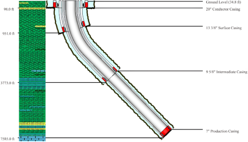
The borehole geometry of the “ARD-01” well is divided into four sections. The Production section, which is the focus of this study, has an inclination angle of 44.45°. The borehole geometry and section parameters are presented in Table 1.
Table 1. Hole Geometry and Well Profil Data.

Parameter

Conductor Section

Surface Section

Intermediate Section

Production Section

Bit Size, in

26

17 ½

12 ¼

8 ½

Casing Size, in

20

13 3/8

9 5/8

7

Length Casing, ft

98

951 MD/ 940.4 TVD

3773 MD/ 3152.9 TVD

7585 MD/ 5612.2 TVD

Inclination °

0

15.11

44.45

44.45

BUR, °/100 ft

0

2.02

0

0

Well trajectory of “ARD-01” well can be seen in Figure 1.
Figure 1. Well Schematic.
2.2. Drill String Data
The drillstring specifications used in the “ARD-01” well, including length, outside diameter, and inside diameter, are presented in Table 2.
Table 2. Drillstring Specifications.

Tools

ID (in)

OD (in)

Length (in)

Drill Pipe

5.00

4.276

6653.78

HWDP 1

5.50

3.625

218.8

Jar

6.50

2.75

31.00

HWDP 2

5.50

3.625

498.69

Drill Collar

6.50

3.00

94.50

Crossover Sub

6.00

2.76

3.00

MWD

6.75

3.00

30.00

LWD

6.75

2.76

30.00

Float Sub

6.75

2.76

3.00

DHMM

6.625

5.50

21.85

2.3. Mud and Well Pump Data
The mud evaluation parameters applied for the 8 1/2” section of Well “ARD-01” are shown in Table 3.
Table 3. Mud Evaluation Data.

Parameter

Data

PV, Cp

28

YP, lb/100ft2

39

µ, cp

65

ρ Cutting, ppg

22

D Cutting, in

1

P Pump, psi

2100

Q Pump, gpm

450

ROP, ft/d

75

RPM

112

WOB, klbs

20

Number of Nozzles

3

TFA, in2

0.59

3. Methods
The research method began with calculating the flow rate that the pump could generate. Next, pressure losses were calculated for each section of the drilling circulation system. These pressure loss values were then used to calculate the hydraulic power generated at the bit, followed by optimization of the downhole mud motor based on the obtained flow rate and motor speed (RPM) parameters. Once the actual conditions are known, hydraulic optimization of the bit is performed with a target ratio of Bit Hydraulic Horsepower to Surface Hydraulic Horsepower (BHHP/HPs) greater than 48% as an indicator of optimal hydraulic conditions at the bit .
3.1. Calculation of Mud Pump Performance
The drilling mud pump used was a National Oilwell Varco (NOV) FD-1000 triplex mud pump with 90% efficiency. A total of two pumps were used, plus one reserve pump, and the pumps were arranged in series at Well “ARD-01,” as shown in Table 4.
Table 4. Mud Pump Specification.

Mud Pump Specification

6 ¾” In Liner

6 ½” In Liner

6 ¼” In Liner

6” In Liner

5 ¾ In Liner

Max Power, HP

1000

1000

1000

1000

1000

Pump Speed, Spm

140

140

140

140

140

Pressure, Psi

2370

2558

2770

3010

3270

Flow Rate, gpm

651

603

558

514

472

The pump specifications indicate a maximum power of 1000 HP with a pump speed of 140 SPM. The liner used has a diameter of 6 ¾ inches, with a working pressure limit of 2370 psi and a flow rate capacity of 651 gpm.
The calculation of the pump’s maximum flow rate is as follows:
Calculate the maximum pump power (HPmax) using Equation (1).
Hpmax= Hp pump x Eff pump x number of pump(1)
Calculate the maximum pump flow rate (Qmax) using Equation (2).
Qmax= Q pump x Eff pump(2)
Calculate the maximum pump pressure (Pmax) using the equation (3).
Pmax= P pump x Eff pump x number of pump(3)
3.2. Calculation of Parasitic Pressure Losses
To calculate surface connections, the surface equipment used during drilling must first be identified. The types of surface equipment used for evaluation at the “ARD-01” well are shown in Table 5 and Table 6.
Table 5. Surface Equipment Type .

Surface Equipment Type

Stand Pipe

Rotary Hose

Swivel

Kelly

Length (ft)

ID (in)

Length (ft)

ID (in)

Length (ft)

ID (in)

Length (ft)

ID (in)

1

40

3.0

40

2.0

4

2.0

40

2.25

2

40

3.5

55

2.5

5

2.5

40

3.25

3

45

4.0

55

3.0

5

2.5

40

3.25

4

45

4.0

55

3.0

6

3.0

40

4.00

Table 6. E Constant Values Based on Surface Connection Type .

Surface Equipment Type

Value of E

Imperial Units

Metric Units

1

2.5 x 10⁻⁴

8.8 x 10⁻⁶

2

9.6 x 10⁻⁵

3.3 x 10⁻⁶

3

5.3 x 10⁻⁵

1.8 x 10⁻⁶

4

4.2 x 10⁻⁵

1.4 x 10⁻⁶

The pressure loss at the surface connection (Psc) is calculated using Equation (4) as follows:
Psc= C ρ0.8 Q1.8 µp0.2(4)
Where:
PSC = Pressure Loss in Surface Connection, psi.
E = Surface Connection Constanta Type.
ρ = Mud Density, ppg.
Q = Flow Rate, gpm.
PV =Plastic viscosity, cp
The hydraulic evaluation method for 8½-inch drilling was performed using the Power Law model. The calculations of pressure loss in each of these components are explained as follows:
Based on the physical properties of drilling mud, the power-law index can be calculated using Equation (5).
n= 3.322log(2PV+YPPV+YP)(5)
Where:
PV = Plastic Viscosity, cp.
YP = Yield Point, 100lb/ft.
Consistency index can be calculated using Equation (6).
K= 510(PV+YP)511n(6)
Where:
n = power law index
PV = Plastic Viscosity, cp.
YP = Yield Point, 100lb/ft.
Calculation of pressure loss in the Inside Drillpipe (Pdp), Heavyweight Drillpipe (Phwdp), and Inside Drillcollar (Pdc) assemblies. Average mud flow velocity in the drillpipe (Vdp) using the Equation (7).
V= Q2.45 d2(7)
Average mud flow velocity in the drill pipe-casing or drillpipe-open hole annulus (VANDP-CSG) using Equation (8).
VANDP= Q2.45 (dh2-dp2)(8)
Critical velocity in the drill pipe (VcDP) using Equation (9).
VcDP=[5.82 104Kρ]12-n[1.6d3n+14n]n2-n(9)
Critical velocity in the drill pipe-casing or drillpipe-open hole annulus (VANDP-CSG) using the Equation (10).
VCANDP= [3.878 104Kρ]12-n[2.4dh-dp2n+13n]n2-n(10)
The Pdp is calculated using the turbulent flow model if v > vc, using the Equation (11).
ΔPdp= 2.27(10-7)ρm0.8V1.8PV0.2Ld1.2(11)
PANDP-CSG or PANDP-OH calculation is performed using the laminar flow model when v < vc, using the Equation (12).
ΔPANDP-CSG=[2.4 Vdh-dp2n+13n]nK L300 (dh-dp)(12)
Where:
Q = Flow Rate, gpm
Dh = Hole Diameter, in
Dp = Pipe Diameter, in
n = power law index
K = concistency index
3.3. Calculation of Downhole Mud Motor
In the 8½-inch drilling string, a 6⅝-inch downhole mud motor was used, with a pressure drop across the motor of 1,050 psi. This pressure drop represents the hydraulic energy used to drive the motor during drilling operations. The operating characteristics of the steerable mud motor used are presented in Table 7.
Table 7. Characteristics of the Motor Power Section.

OD (in)

Lobes

Flow Rate (gpm)

Pressure Drop (psi)

Speed Range (RPM)

RPG

6 ¾

4:5

300-600

875

149-300

0.50

6 ¾

7:8

300-600

415

42-84

0.15

6 ¾

7:8

300-600

1000

150-300

0.28

6 5/8

5:6

450-750

1330

155-258

0.34

6 5/8

4:6

350-700

1350

1220-280

0.40

6 5/8

5:6

350-700

1250

123-245

0.35

6 5/8

7:8

300-700

1050

75-175

0.25

Calculation of total pressure loss before the series using Equation (13).
ΔPinlet = ΔP1+ΔP2+ΔP3(13)
Inlet pressure (Pinlet) of the motor can be calculated using Equation (14).
Pinlet = P-ΔPinlet(14)
Power of a motor (HPmotor) can be calculated using the following equation (15).
Hp = Pmotor Q1714(15)
RPM of the DHMM can be calculated using Equation (16).
RPM= RPG x Q(16)
Where:
P = Pressure, psi
Q = Flow Rate, gpm
RPG = Revolution per Gallon
3.4. Calculation of BHHP and HPs
The pressure loss at the bit (Pb) must first be calculated using Equation (17).
Pb=Pdata-Pp(17)
BHHP value can be calculated as follows using Equation (18).
BHHP=PbQ1714(18)
HPs value can be calculated as follows using Equation (19).
HPs=Pm x Qopt1714(19)
The effectiveness of hydraulic energy transfer to the bit was assessed using the ratio of actual BHHP to surface pump power (HPs), as shown in the following Equation (20).
BHHP/HPs(%)=BHHPHPsx 100%(20)
Where:
Pb = Pressure Loss on Bit, Psi
Pp = Parasitic Pressure, psi
Pm = Maximum of Surface Pressure, Psi
4. Results
The results of the calculations for the maximum flow rate of two triplex pumps connected in series are presented in Table 8.
Table 8. Results of the Pump Flow Rate and Pressure Evaluation.

Parameters

Result

Hp Max, Hp

2000

Q Max, gpm

585.9

P Max, Psi

4266

These calculations include an evaluation of the mud flow velocity within the drillstring and the annulus, as well as the identification of the flow regime (laminar or turbulent) based on a comparison between the average velocity and the critical velocity . The calculations were performed for the 8½-inch section down to a depth of 7.585 ft MD.
Table 9. Pressure Loss Evaluation Calculation Results.

Parameters

Pressure Loss (Psi)

Surface Connection

43.45

Drill Pipe

366.84

HWDP

147.357

Drill Collar

64.39

DHMM

1050

Annulus Drill Pipe

203.17

Annulus HWDP

39.34

Annulus Drill Collar

25.51

For a total pressure loss of 1939.721 psi, the actual pump pressure used on the 8½-inch section was 2100 psi.
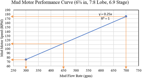
The relationship between flow rate and the downhole mud motor’s rotational speed (RPM) is shown in Figure 2.
Figure 2. Relationship between Flow Rate and Downhole Mud Motor RPM.
As can be seen in the figure, the regression results or equation obtained can be used to calculate the motor speed based on the actual flow rate. At the minimum motor speed of 75 rpm, the minimum flow rate is 300 gpm; at the maximum motor speed of 175 rpm, the maximum flow rate is 700 gpm; and at the operating motor speed of 112.5 rpm, the operating flow rate is 450 gpm.
The results of the hydraulic evaluation of the cutter are presented in Table 10.
Table 10. Results of the Hydraulic Evaluation of Drilling on Bit Using the BHHP Method.

Parameters

Result

Pressure Loss Bit, Psi

160.278

BHHP/HPs, %

7.63

Based on the results of the hydraulic evaluation of the bit, a BHHP/HPs ratio of 7.63% was obtained. This value indicates that the hydraulic conditions have not yet reached an optimal state, as the BHHP/HPs ratio remains below the optimal limit of 48%.
The optimization calculations for the drill bit begin by determining the optimal rotational speed (RPM) and flow rate, followed by a sensitivity analysis regarding pump pressure. Initially, a single pump unit was used to evaluate the system under actual operating conditions, covering a pressure range up to 2100 psi. To achieve higher hydraulic performance, a second pump unit was then connected in series, thereby expanding the operating pressure range from 2100 to 4200 psi. A third pump, serving as a backup unit, was added in series, bringing the total to three pump units and enabling the system to operate within a pressure range of 4200 to 6300 psi. This staged pump configuration was implemented to achieve the required pump pressure to meet hydraulic requirements throughout the optimization path, as presented in Table 11.
Table 11. Results of Trial and Error Bit Hydraulic Optimization for Well “ARD-01”.

P (Psi)

Q (gpm)

RPM

(P x Q)/1714 (HP)

BHHP (HP)

HPs (HP)

BHHP/HPs (%)

2100

450

112

551.342

42.08

551.34

7.63

2600

530

132

803.967

131.21

803.96

16.32

3100

530

132

958.576

285.82

958.57

29.82

3600

530

132

1113.19

440.42

113.19

39.56

4200

530

132

1298.72

625.96

1298.71

48.20

4700

530

132

1453.33

780.56

1453.33

53.71

5200

530

132

1607.93

935.17

1607.93

58.16

5700

530

132

1762.54

1089.78

1762.54

61.83

6300

530

132

1948.07

1275.31

1275.31

65.47

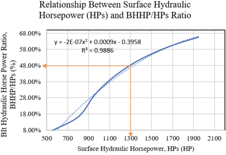
Figure 3. Relationship between Surface Hydraulic Horsepower and the BHHP/HPs Ratio.
Based on the trial and error results shown in the table, the hydraulic optimization of the bit indicates optimal conditions at a pump pressure of 4200 psi, in a scenario using only two pumps, a BHHP/HPs ratio of 48.20% was obtained. Figure 3 shows the relationship between the value of (P×Q)/1,714 and the BHHP/HPs ratio.
5. Discussion
The results of the hydraulic drill bit evaluation conducted on the 8½-inch section of Well “ARD-01” indicate that the hydraulic drill bit system is not yet operating under optimal conditions. The Bit Hydraulic Horsepower to Surface Hydraulic Horsepower (BHHP/HPs) ratio was 7.63%, which is below the optimal value of 48%, resulting in a penetration rate of only 75 ft/hr and a motor speed of just 112 rpm. These results indicate that a significant portion of the hydraulic energy is lost as pressure loss throughout the circulation system, thereby limiting the hydraulic power transmitted to the bit. Consequently, the energy generated at the bit is insufficient to effectively clear the bottom of the borehole, resulting in suboptimal removal of cuttings from the bottom of the borehole. Increasing WOB is not feasible because it could trigger a pendulum effect, which would cause a decrease in inclination and interfere with achieving the target wellbore trajectory. Therefore, efforts to improve drilling performance must focus on increasing motor rotational speed (RPM) through hydraulic optimization, so that the limitations of WOB can be offset by optimizing the hydraulic energy received by the downhole mud motor, thereby resulting in an increase in ROP.
The hydraulic during directional drilling must provide a BHHP/HPs ratio close to 48%, since a portion of the hydraulic horsepower approximately 18% is used to operate the downhole mud motor. This correlation determines the desired drilling rate, particularly in the design of the downhole mud motor, to ensure an adequate RPM (mechanical factor). There are limitations on weight on bit, as this load can cause the borehole to deviate from its intended direction. This issue must be resolved by adjusting the flow rate to provide a sufficient rpm range within the motor’s capacity . This plan outlines the correlation between the downhole mud motor’s flow rate and the mechanical factor, ensuring that the hydraulic system in the drill bit can effectively clear cuttings from the bottom of the borehole. The RPM range must provide flexibility or room for increasing the RPM.
Pressure drop in the circulation system also affects the hydraulic performance of the bit. The downhole mud motor causes a pressure drop of 1,050 psi, thereby reducing the hydraulic energy available to the bit. In directional drilling, low hydraulic energy reaching the bit can lead to the accumulation of cuttings around the wellbore bottom . The downhole mud motor plays a crucial role in directional drilling because it can rotate the bit directly without having to rotate the entire drill string.
This study focuses on the use of a downhole mud motor with an operating range that still allows for an increase in flow rate and motor speed (RPM) without exceeding design limits or potentially damaging the motor. Therefore, a 6⅝ inch downhole mud motor with a flow rate range of 300–700 gpm and a rotational speed range of 75–175 rpm was selected. This operating range provides the flexibility to increase motor RPM to compensate for limitations in increasing Weight on Bit (WOB), thereby allowing the mechanical drilling load to be increased through higher RPM without affecting the drilling trajectory such as changes in dogleg severity or the angle of inclination toward the target reservoir.
Through a trial-and-error approach, hydraulic optimization was achieved by increasing the mud flow rate from 450 gpm to 530 gpm and raising the motor speed from 112 rpm to 132 rpm, thereby maintaining the downhole mud motor’s mechanical speed within the desired operating range. To meet pressure requirements during the optimization process, three mud pump units were operated in series, increasing pump pressure from 2,100 psi to 4,200 psi. The optimization results showed that the ratio of Bit Hydraulic Horsepower to Surface Hydraulic Horsepower (BHHP/HPs) increased from 7.63% to 48.20%, indicating that the hydraulic energy transmitted to the bit had reached optimal conditions. This improvement not only enhanced the hydraulic energy efficiency at the bit but also maintained the downhole mud motor’s performance at the expected operating speed.
Although this study did not directly evaluate changes in the Rate of Penetration (ROP), the increase in hydraulic efficiency of the drill bit, as indicated by a BHHP/HPs ratio of 48.20%, is expected to have a positive effect on the drilling rate. This result is consistent with the concept proposed in , which states that an increase in hydraulic energy in the drill bit can improve the bottom-hole cleaning process, thereby making the rock crushing process more effective. also report that optimal distribution of hydraulic energy in the drill bit can improve drilling efficiency through better cuttings clearance and reduced bit balling. Even though this study does not directly evaluate changes in the Rate of Penetration (ROP), optimization of the drill bit’s hydraulics is expected to improve the drilling rate reported that in limestone formations, hydraulic optimization can increase the average ROP by approximately 20%, with a maximum increase of up to 40%. Therefore, an initial ROP of 75 ft/hr theoretically has the potential to increase to about 90 ft/hr under average conditions, or up to 105 ft/hr under optimal conditions. This increase in ROP has the potential to shorten drilling time, thereby reducing both the duration of operations and drilling costs.
Improved hydraulic performance in the drill bit can result in better bottom-hole cleaning, thereby reducing the risk of cuttings buildup at the bottom of the borehole and potentially lowering the risk of bit balling and cuttings regrinding during directional drilling operations using a downhole mud motor. These results indicate that the distribution of hydraulic power is more balanced between the demands of the downhole mud motor and the drill bit, allowing for improved effectiveness in cuttings removal from the bottom of the borehole.
6. Conclusion
The results of the hydraulic bit evaluation on the 8½-inch section of Well “ARD-01” indicate that the hydraulic bit system is not yet operating optimally, as evidenced by a Bit Hydraulic Horsepower to Surface Hydraulic Horsepower (BHHP/HPs) ratio of 7.63%, which is far below the optimal value of 48%. This condition causes most of the hydraulic energy to be lost as pressure loss in the circulation system, resulting in insufficient hydraulic power being transmitted to the bit to effectively clean the wellbore bottom. In directional drilling, increasing the Weight on Bit (WOB) is not feasible because it could potentially cause a pendulum effect that might interfere with achieving the target wellbore trajectory; therefore, efforts to improve drilling performance must focus on increasing the downhole mud motor speed through hydraulic optimization.
Through a trial-and-error approach, optimization was achieved by increasing the mud flow rate from 450 gpm to 530 gpm and raising the motor speed from 112 rpm to 132 rpm, as well as operating three mud pump units in series to increase pump pressure from 2100 psi to, 200 psi. The optimization results showed that the BHHP/HPs ratio increased from 7.63% to 48.20%, indicating that the hydraulic energy transmitted to the bit had reached optimal conditions and was capable of maintaining the downhole mud motor’s performance at the expected operating speed.
Improving the hydraulic efficiency of the drill bit is expected to have a positive impact on the drilling rate through more effective wellbore cleaning, thereby potentially increasing the Rate of Penetration (ROP), reducing the risk of bit balling and cuttings regrinding, improving cuttings removal from the wellbore, and reducing both the time and cost of drilling operations.
Abbreviations

BHHP

Bit Hydraulics Horsepower

HPs

Horsepower Surface

RPM

Revolution Per Minute

BUR

Build Up Rate

DHMM

Downhole Mud Motor

MD

Measure Depth

TVD

True Vertical Depth

P

Pressure

Q

Flow Rate

n

Flow Index

K

Consistency Index

PV

Plastic Viscosity

YP

Yield Point

Author Contributions
Herianto: Conceptualization, Data curation, Formal Analysis, Investigation, Methodology, Validation, Visualization, Writing – original draft, Writing – review & editing
Rivandi Ardanda Adiguna: Conceptualization, Data curation, Formal Analysis, Investigation, Methodology, Validation, Visualization, Writing – original draft
Conflicts of Interest
The author declares no conflicts of interest.
References
[1] Khudhair, S.; Al-Mahdawi, F. H. M. Optimization of Drilling Well Design: A Review. Iraqi Journal of Chemical and Petroleum Engineering 2022, 23(4), 91–99.
[2] S. K. Al-Hlaichi and F. H. M. Al-Mahdawi, “Drilling optimization by using high drilling techniques: A review,” AIP Conf. Proc., vol. 2839, no. 1, p. 20029, Sep. 2023,
[3] J. Skenderija, A. Koulidis, D. L. Sanchez, and S. Ahmed, “Advanced Hole Cleaning in Horizontal Wells: Experimental Investigation Supported by a Downhole Clamp-On Tool,” Feb. 19, 2023.
[4] Y. Wang and S. Salehi, “Application of Real-Time Field Data to Optimize Drilling Hydraulics Using Neural Network Approach,” J. Energy Resour. Technol., vol. 137, no. 6, Nov. 2015,
[5] G. Gjelstad, G. Hareland, K. N. Nikolaisen, and R. K. Bratli, “The Method of Reducing Drilling Costs More Than 50 Percent,” Jul. 08, 1998.
[6] M. Alinejad Mofrad, Drilling Hydraulics Simulation Analysis and Comparison to a Field Case. 2006.
[7] R. Ashena, A. A. Hekmatinia, A. Ghalambor, B. Aadnoy, C. Enget, and V. Rasouli, “Improving drilling hydraulics estimations-a case study,” J. Pet. Explor. Prod. Technol., vol. 11, no. 6, pp. 2763–2776, 2021,
[8] T. C. Nguyen, E. Al-Safran, and V. Nguyen, “Theoretical modeling of Positive Displacement Motors performance,” J. Pet. Sci. Eng., vol. 166, no. December 2017, pp. 188–197, 2018,
[9] A. Y. Prawira and E. P. Rini, “Size and configuration of mud motor drilling affects the optimum power outputs,” Eng. Solid Mech., vol. 5, no. 2, pp. 93–102, 2017,
[10] D. Belov et al., “Hybrid Approach for Health Monitoring of Mud Motor Fleet,” PHM Soc. Eur. Conf., vol. 6, no. 1, p. 10, Jun. 2021,
[11] S. Irawan, A. M. Abd Rahman, and S. Q. Tunio, “Optimization of weight on bit during drilling operation based on rate of penetration model,” Res. J. Appl. Sci. Eng. Technol., vol. 4, no. 12, pp. 1690–1695, 2012,
[12] M. M. Al Rubaii, “A new robust approach for hole cleaning to improve rate of penetration,” Soc. Pet. Eng. - SPE Kingdom Saudi Arab. Annu. Tech. Symp. Exhib. 2018, SATS 2018, 2018,
[13] A. Kiyani, P. Moarefvand, M. Dehvedar, and M. K. Moraveji, “Computational Fluid Dynamic application on Bit Hydraulic Performance,” Int. Conf. Recent Innov. n Chem. Chem. Eng., vol. 4, no. July 2017, pp. 1–16, 2017.
[14] S. BA, D. Belov, D. Nobre, L. L. Yin, and E. Johnson, “Combined Data Analytics and Physics-Based Simulation for Optimum Bit, Motor, BHA Combination,” Oct. 29, 2019.
[15] Shamsuddin, M. N.; Busahmin, B. Drilling Optimization through Rig Hydraulics Using a Mathematical Model. Improved Oil and Gas Recovery 2025, 9, 1–10.
[16] Al-Rubaii, M. M. Real-Time Models of Rig and Drill Bit Hydraulics Optimizes Drilling Efficiency. In Offshore Technology Conference Asia; Kuala Lumpur, Malaysia, 2026.
[17] H. Widiyatni, A. Rizkina, and W. I. Dirastri, “Evaluation of drilling hydraulic calculation to the ability of bottom hole cleaning,” J. Phys. Conf. Ser., vol. 1402, no. 5, pp. 0–6, 2019,
[18] Herianto, “Optimization of Hydraulic Horsepower to Predict the Rate of Penetration,” Am. J. Phys. Appl., vol. 6, no. 3, p. 63, 2018,
[19] Herianto, “Optimization Rate Of Penetration In Directional Drilling With Adjustable Bit Rotating and Hydraulic Hole Cleaning,” Adv. Image Video Process., vol. 9, no. 5, 2021,
[20] H. Rabia, Oilwell drilling engineering : principles and practice / by H. Rabia. London: London: Graham & Trotman, 1985.
[21] J. Bourgoyne, K. K. Millheim, M. E. Chenevert, and J. Young F S, Applied drilling engineering. United States: Richardson, TX (United States); Society of Petroleum Engineers, 1986. [Online]. Available:
Cite This Article
  • APA Style

    Herianto, Adiguna, R. A. (2026). Integrated Drill Bit Hydraulic Optimization and Mechanical Factor for Directional Drilling. Science Discovery, 14(4), 297-306. https://doi.org/10.11648/j.sd.20261404.25

    Copy | Download

    ACS Style

    Herianto; Adiguna, R. A. Integrated Drill Bit Hydraulic Optimization and Mechanical Factor for Directional Drilling. Sci. Discov. 2026, 14(4), 297-306. doi: 10.11648/j.sd.20261404.25

    Copy | Download

    AMA Style

    Herianto, Adiguna RA. Integrated Drill Bit Hydraulic Optimization and Mechanical Factor for Directional Drilling. Sci Discov. 2026;14(4):297-306. doi: 10.11648/j.sd.20261404.25

    Copy | Download

  • @article{10.11648/j.sd.20261404.25,
      author = {Herianto and Rivandi Ardanda Adiguna},
      title = {Integrated Drill Bit Hydraulic Optimization and Mechanical Factor for Directional Drilling},
      journal = {Science Discovery},
      volume = {14},
      number = {4},
      pages = {297-306},
      doi = {10.11648/j.sd.20261404.25},
      url = {https://doi.org/10.11648/j.sd.20261404.25},
      eprint = {https://article.sciencepublishinggroup.com/pdf/10.11648.j.sd.20261404.25},
      abstract = {The “ARD-01” well is a directional well with a final depth of 7,585 ftMD, penetrating the limestone Tuban Formation. At the 8 ½” section, a drilling issue arose in the form of a suboptimal hydraulic program due to insufficient bit power, as indicated by a BHHP/HPs ratio of 7.63%. Under these conditions, the downhole mud motor operated at 112.5 rpm with a Rate of Penetration (ROP) of 75 ft/hr, which could potentially lead to bit balling and cutting regrinding due to cuttings buildup in the borehole, thereby reducing rock fragmentation efficiency and increasing the risk of non-productive time (NPT). The hydraulic evaluation and optimization conducted in this study utilized the Bit Hydraulic Horsepower (BHHP) method, which is considered effective because it focuses on the total hydraulic energy that aids in cuttings removal. BHHP accounts for the combination of pressure and flow rate, with a target BHHP/HPs ratio of approximately 48%, since a portion of the hydraulic horsepower, around 18% is used to operate the downhole mud motor. This relationship determines the desired drilling rate, particularly in the design of the downhole mud motor, to ensure adequate rotational speed (RPM) as a mechanical factor. The results of drilling hydraulics optimization achieved by changing the actual flow rate from 450 gpm to an optimized flow rate of 530 gpm and the actual pressure from 2100 to an optimized pressure of 4200 psi using a series connected triplex pump yielded an increase in the BHHP/HPs ratio of 48.20% which meets the recommended hydraulic parameters for directional drilling with a downhole mud motor. Under these conditions, the downhole mud motor speed increased to 132 rpm, resulting in a Rate of Penetration (ROP) increase from 75 ft/hr to 90 ft/hr under average conditions and reaching 105 ft/hr under optimal conditions. These results indicate that optimizing pressure and flow rate using the BHHP method can increase the hydraulic energy available at the bit, thereby improving drilling efficiency.},
     year = {2026}
    }
    

    Copy | Download

  • TY  - JOUR
    T1  - Integrated Drill Bit Hydraulic Optimization and Mechanical Factor for Directional Drilling
    AU  - Herianto
    AU  - Rivandi Ardanda Adiguna
    Y1  - 2026/08/18
    PY  - 2026
    N1  - https://doi.org/10.11648/j.sd.20261404.25
    DO  - 10.11648/j.sd.20261404.25
    T2  - Science Discovery
    JF  - Science Discovery
    JO  - Science Discovery
    SP  - 297
    EP  - 306
    PB  - Science Publishing Group
    SN  - 2331-0650
    UR  - https://doi.org/10.11648/j.sd.20261404.25
    AB  - The “ARD-01” well is a directional well with a final depth of 7,585 ftMD, penetrating the limestone Tuban Formation. At the 8 ½” section, a drilling issue arose in the form of a suboptimal hydraulic program due to insufficient bit power, as indicated by a BHHP/HPs ratio of 7.63%. Under these conditions, the downhole mud motor operated at 112.5 rpm with a Rate of Penetration (ROP) of 75 ft/hr, which could potentially lead to bit balling and cutting regrinding due to cuttings buildup in the borehole, thereby reducing rock fragmentation efficiency and increasing the risk of non-productive time (NPT). The hydraulic evaluation and optimization conducted in this study utilized the Bit Hydraulic Horsepower (BHHP) method, which is considered effective because it focuses on the total hydraulic energy that aids in cuttings removal. BHHP accounts for the combination of pressure and flow rate, with a target BHHP/HPs ratio of approximately 48%, since a portion of the hydraulic horsepower, around 18% is used to operate the downhole mud motor. This relationship determines the desired drilling rate, particularly in the design of the downhole mud motor, to ensure adequate rotational speed (RPM) as a mechanical factor. The results of drilling hydraulics optimization achieved by changing the actual flow rate from 450 gpm to an optimized flow rate of 530 gpm and the actual pressure from 2100 to an optimized pressure of 4200 psi using a series connected triplex pump yielded an increase in the BHHP/HPs ratio of 48.20% which meets the recommended hydraulic parameters for directional drilling with a downhole mud motor. Under these conditions, the downhole mud motor speed increased to 132 rpm, resulting in a Rate of Penetration (ROP) increase from 75 ft/hr to 90 ft/hr under average conditions and reaching 105 ft/hr under optimal conditions. These results indicate that optimizing pressure and flow rate using the BHHP method can increase the hydraulic energy available at the bit, thereby improving drilling efficiency.
    VL  - 14
    IS  - 4
    ER  - 

    Copy | Download

Author Information
  • Department of Petroleum Engineering, UPN "Veteran" Yogyakarta, Yogyakarta, Indonesia

    Biography: Herianto is a Professor of Petroleum Engineering at Universitas Pembangunan Nasional "Veteran" Yogyakarta, Indonesia. He received his B.Eng. in Petroleum Engineering from UPN "Veteran" Yogyakarta, an M.Sc. in Petroleum Engineering from Institut Teknologi Bandung (ITB), and a Ph.D. in Petroleum Engineering from Universiti Teknologi Malaysia (UTM). His research interests include drilling engineering, geothermal engineering, petroleum field management, energy economics, and drilling management. He has served as an international instructor and senior consultant for major oil and gas companies and government institutions, including Pertamina, Chevron, PetroChina, Repsol, ConocoPhillips, and the Directorate General of Oil and Gas. He is also actively involved in national energy and geothermal development projects and holds the Insinyur Profesional Utama (IPU) certification awarded by the Institution of Engineers Indonesia (PII)

    Research Fields: M.Sc., IPU: Petroleum drilling engineering, Geothermal engineering, Petroleum field management, Energy economics, Drilling management, Well control engineering, Reservoir engineering, Oil and gas production, Petroleum engineering education, National energy policy

  • Department of Petroleum Engineering, UPN "Veteran" Yogyakarta, Yogyakarta, Indonesia

    Biography: Rivandi Ardanda Adiguna is an undergraduate student in the Department of Petroleum Engineering at Universitas Pembangunan Nasional "Veteran" Yogyakarta, Indonesia. His research interests include drilling engineering, drilling hydraulics, and directional drilling. He has served as a Teaching Assistant in the Drilling Laboratory and completed an industrial internship at Pertamina EP Zona 11 Cepu Field, where he gained practical experience through the review of the Acid Gas Removal Unit (AGRU) at the Central Processing Plant (CPP) Gundih. His current research focuses on hydraulic optimization based on Bit Hydraulic Horsepower (BHHP) analysis to improve drilling performance in directional wells.

    Research Fields: Drilling engineering, Drilling hydraulics, Directional drilling, Drilling optimization


  • Abstract
  • Keywords
  • Document Sections

    1. 1. Introduction
    2. 2. Material
    3. 3. Methods
    4. 4. Results
    5. 5. Discussion
    6. 6. Conclusion
    Show Full Outline
  • Abbreviations
  • Author Contributions
  • Conflicts of Interest
  • References
  • Cite This Article
  • Author Information