Abstract
Reliable static firing facilities are indispensable for evaluating the performance, structural integrity, and operational safety of solid rocket motors (SRMs). However, the high cost and limited availability of dedicated propulsion test facilities continue to constrain experimental rocket propulsion research in many developing countries. This study presents the design, fabrication, and structural validation of a cost-effective mobile static test stand developed at the Advanced Aerospace Engines Laboratory (AAEL) in Nigeria to support indigenous solid rocket motor research and development. The developed facility integrates a rigid steel support structure, an adjustable motor mounting assembly, a centrally mounted compression load cell, a dedicated thrust data acquisition system, a programmable remote ignition controller, and a reinforced steel safety cage equipped with wireless 4K night-vision cameras for real-time remote monitoring. The ignition system incorporates a programmable 30-second countdown sequence, an audible warning alarm, wireless remote firing capability over distances up to 400 m, and an emergency abort function to enhance operational safety. The structural components of the test stand were designed using conventional mechanical design principles and validated through finite element analysis to ensure adequate stiffness and structural integrity under the maximum expected loading conditions. Real-time thrust measurements are obtained through a calibrated compression load cell integrated with a dedicated data acquisition system capable of continuously recording thrust throughout the combustion process. The developed test facility provides a practical, reliable, and economically sustainable platform for the experimental evaluation of solid rocket motors developed within Nigeria's indigenous space programme.
Keywords
Solid Rocket Motor, Static Firing Test Stand, Thrust Measurement, Mobile Propulsion Testing, Data Acquisition,
Remote Ignition System, Structural Design, Aerospace Testing
1. Introduction
Static firing testing is one of the most important experimental procedures in the development and qualification of solid rocket propulsion systems
| [1] | Krows, A.; Wooten, J.; Smith, A.; Halley, D.; Shavezipur, D. K. Design And Simulation of a Static Fire Test Stand for Solid Rocket Motor Testing. In 2025 Regional Student Conferences; American Institute of Aeronautics and Astronautics, 2025.
https://doi.org/10.2514/6.2025-99377 |
[1]
. It provides direct measurement of thrust-time history, burn duration, total impulse, and overall motor performance whilst enabling verification of analytical predictions, validation of numerical models, and assessment of combustion stability under controlled operating conditions
| [2] | Fernandes, F. A. C.; Souto, C. d’Andrade; Pirk, R. Static Firing Tests of Solid Propellant Rocket Motors: Uncertainty Levels of Thrust Measurements. J. Aerosp. Technol. Manag. 2022, 14, e2022. https://doi.org/10.1590/jatm.v14.1270 |
[2]
. Freeman (2018) emphasised that static fire tests are essential for assessing thrust measurement uncertainty, including motor alignment, load cell dynamics, signal conditioning, and calibration procedures, which collectively determine the reliability of experimental propulsion data
. As such, every stage of solid rocket motor development—from laboratory-scale research to flight qualification—depends on reliable static firing facilities
| [4] | Migliorino, M. T.; Aiello, M.; Berti, M.; Rotondi, M.; D’Alessandro, S.; Bianchi, D.; Jahjah, M.; Pizzarelli, M. Student Firing Tests and Launches with Commercial and Self-Made Solid Rocket Motors. Acta Astronaut. 2022, 197, 23–34.
https://doi.org/10.1016/j.actaastro.2022.04.025 |
[4]
.
Despite the importance of static testing, the availability of dedicated propulsion test facilities remains limited in many developing countries
| [4] | Migliorino, M. T.; Aiello, M.; Berti, M.; Rotondi, M.; D’Alessandro, S.; Bianchi, D.; Jahjah, M.; Pizzarelli, M. Student Firing Tests and Launches with Commercial and Self-Made Solid Rocket Motors. Acta Astronaut. 2022, 197, 23–34.
https://doi.org/10.1016/j.actaastro.2022.04.025 |
[4]
. The construction of permanent static firing installations requires substantial financial investment in reinforced structures, instrumentation, safety systems, and supporting infrastructure. Dobrodomov et al. (2026) noted that the growing need for solid propellant boosters for unmanned aerial vehicles and small rocket systems, combined with limited access to industrial experimental facilities, has motivated the development of low-cost and high-precision test stands
| [5] | Dobrodomov, O.; Proroka, V.; Dobrodomov, O.; Shvets, A.; Dalik, M.; Bilotserkovskyi, I. UNIVERSAL HIGH-PRECISION THRUST STAND FOR SOLID ROCKET MOTOR STATIC FIRE TESTS. J. Rocket-Space Technol. 2026, 35 (1), 8–13. https://doi.org/10.15421/452557 |
[5]
. These requirements often exceed the resources available to research institutions and universities, thereby limiting experimental activities and slowing technological development.
In Nigeria, indigenous research into rocket propulsion has expanded considerably over the past decade as part of the national effort to strengthen space transportation capability. This initiative is led by the National Space Research and Development Agency (NASRDA) through its Bola Ahmed Tinubu Centre for Space Transport and Propulsion (BAT-CSTP) and associated engineering laboratories.
The Advanced Aerospace Engines Laboratory (AAEL) was established on 24 April 2017 as one of the specialised engineering laboratories under BAT-CSTP to accelerate research and development in aerospace propulsion technologies in support of the Federal Government's long-term space development roadmap. The laboratory is mandated to conduct research in launch vehicle propulsion systems, spacecraft propulsion, satellite manoeuvring engines, and related aerospace propulsion technologies. Since its establishment, AAEL has successfully undertaken several indigenous propulsion development programmes, including solid rocket motors, cold-gas propulsion systems, liquid propulsion technologies, and associated propulsion testing infrastructure.
One of the major challenges encountered during these programmes has been the absence of a dedicated, locally developed static firing facility capable of safely evaluating experimental rocket motors whilst providing accurate thrust measurements under field conditions. Commercial propulsion testing facilities are expensive, difficult to procure, and often unsuitable for local research requirements
| [6] | Miao, Y.; Wang, G.; Rui, X.; Tu, T. Study on Test Dynamics Method of Non-Full Loading Firing for Multiple Launch Rocket System. Mech. Syst. Signal Process. 2019, 122, 463–479. https://doi.org/10.1016/j.ymssp.2018.12.043 |
[6]
. Nakka (2000) addressed similar constraints by developing the STS-5000 Static Test Stand, a lightweight, portable tripod-based stand fabricated from metal tubes, designed for testing motors with thrust up to 5000 N, which remained in use for over two decades
. Consequently, there exists a clear need for an indigenous, cost-effective, and portable test platform capable of supporting propulsion research within the available technical and economic constraints.
The work presented in this paper addresses this challenge through the design, fabrication, instrumentation, and structural validation of a mobile static firing test stand specifically developed for solid rocket motor testing at AAEL. The system integrates mechanical, electrical, instrumentation, and safety subsystems into a compact experimental platform capable of conducting repeatable static firing experiments whilst ensuring operator safety through remote ignition, real-time data acquisition, and reinforced fragment containment.
1.1. Review of Existing Literature
Static firing test facilities have evolved significantly over the past several decades, ranging from large permanent installations used by government space agencies to compact laboratory-scale systems developed for academic research.
Large propulsion laboratories, including those operated by NASA, ESA, ISRO, JAXA, and other national space agencies, employ heavily reinforced fixed test facilities designed for high-thrust rocket motors. These installations typically incorporate massive reaction structures, advanced instrumentation, automated control systems, blast-resistant enclosures, and sophisticated data acquisition architectures capable of supporting full-scale launch vehicle development. The NASA Rocket Engine Test Facility (RETF), constructed in 1957 at $2.5 million, represented the largest high-energy test facility in the United States at the time, featuring a vertical test cell, control centre, and large scrubber for toxic byproduct removal
. Although these facilities provide exceptional measurement accuracy and operational safety, their construction and maintenance costs place them beyond the reach of many universities and emerging aerospace programmes.
To address these limitations, universities and research organisations have developed smaller and more economical static test facilities for laboratory-scale propulsion research
| [4] | Migliorino, M. T.; Aiello, M.; Berti, M.; Rotondi, M.; D’Alessandro, S.; Bianchi, D.; Jahjah, M.; Pizzarelli, M. Student Firing Tests and Launches with Commercial and Self-Made Solid Rocket Motors. Acta Astronaut. 2022, 197, 23–34.
https://doi.org/10.1016/j.actaastro.2022.04.025 |
| [9] | Netzel, N. A.; Batista, D. S.; Granziera Jr., F.; Tosin, M. C. A Versatile Low-Cost Data Acquisition System for Small Rocket Engine Test Bench. HardwareX 2025, 23, e00686.
https://doi.org/10.1016/j.ohx.2025.e00686 |
| [11] | Prodan, M. Design of test benches for cryogenic hybrid rocket engines. laurea, Politecnico di Torino, 2025.
https://webthesis.biblio.polito.it/37495/ (accessed 2026-07-30). |
[4, 9–11]
. Educational test stands generally employ welded steel structures, compression or tension load cells, modular motor mounting assemblies, and computer-based data acquisition systems to characterise thrust performance
| [4] | Migliorino, M. T.; Aiello, M.; Berti, M.; Rotondi, M.; D’Alessandro, S.; Bianchi, D.; Jahjah, M.; Pizzarelli, M. Student Firing Tests and Launches with Commercial and Self-Made Solid Rocket Motors. Acta Astronaut. 2022, 197, 23–34.
https://doi.org/10.1016/j.actaastro.2022.04.025 |
| [12] | Murphy, J. J.; Tuck-Lee, J. P.; Tovar, J. M.; Stubblebine, M. J.; Goyal, V. K. Evaluation and Test Requirements for Solid Rocket Motors. 2023. |
[4, 12]
. Jayaram (2022) described the development of a versatile data acquisition system for collegiate hybrid and solid rocketry, employing Arduino and National Instruments hardware to measure thrust, chamber pressure, tank pressure, and mass flow, emphasising the importance of mobility and sensor interchangeability for safe testing operations
| [13] | Jayaram, S.; Pritzlaff, H.; Stack, A. Data Acquisition for Collegiate Hybrid and Solid Rocketry - An Undergraduate Research Experience; 2022. |
[13]
. These systems emphasise affordability, portability, and ease of fabrication while maintaining sufficient measurement accuracy for experimental propulsion investigations
| [9] | Netzel, N. A.; Batista, D. S.; Granziera Jr., F.; Tosin, M. C. A Versatile Low-Cost Data Acquisition System for Small Rocket Engine Test Bench. HardwareX 2025, 23, e00686.
https://doi.org/10.1016/j.ohx.2025.e00686 |
[9]
. Recent developments have also focused on improving operational safety through remote ignition systems, wireless monitoring technologies, automated countdown procedures, and integrated safety interlocks
| [1] | Krows, A.; Wooten, J.; Smith, A.; Halley, D.; Shavezipur, D. K. Design And Simulation of a Static Fire Test Stand for Solid Rocket Motor Testing. In 2025 Regional Student Conferences; American Institute of Aeronautics and Astronautics, 2025.
https://doi.org/10.2514/6.2025-99377 |
[1]
. Advances in digital instrumentation have enabled real-time thrust measurement, automated calibration, synchronised video acquisition, and post-test performance analysis using commercially available data acquisition hardware and software
| [5] | Dobrodomov, O.; Proroka, V.; Dobrodomov, O.; Shvets, A.; Dalik, M.; Bilotserkovskyi, I. UNIVERSAL HIGH-PRECISION THRUST STAND FOR SOLID ROCKET MOTOR STATIC FIRE TESTS. J. Rocket-Space Technol. 2026, 35 (1), 8–13. https://doi.org/10.15421/452557 |
| [14] | James, M. Computer Vision of Analog Gauges as an Alternative to Digital Flight Test Instrumentation. Theses Diss. 2022. |
[5, 14]
.
Netzel et al. (2025) presented a versatile low-cost data acquisition system for small rocket motor testing, capable of measuring thrust and pressure through load cell sensors and pressure transducers, with a modular design prioritising adaptability for university research environments
| [9] | Netzel, N. A.; Batista, D. S.; Granziera Jr., F.; Tosin, M. C. A Versatile Low-Cost Data Acquisition System for Small Rocket Engine Test Bench. HardwareX 2025, 23, e00686.
https://doi.org/10.1016/j.ohx.2025.e00686 |
[9]
. Montoro et al. (2025) demonstrated the application of integrated data acquisition solutions in static fire testing, capturing high-quality thrust and temperature data while reducing ignition time through synchronised multi-sensor recording
. Verma (2022) described a static test pad employing Arduino-controlled remote ignition via NRF modules, with load cells and HX711 amplifiers for thrust measurement, illustrating the trend toward low-cost, programmable test infrastructure
. Although significant progress has been made internationally, relatively few published studies describe the complete design and indigenous fabrication of mobile static firing facilities suitable for propulsion research within developing countries. In particular, there remains limited documentation of integrated systems combining structural design, thrust measurement, remote ignition, data acquisition, and fragment containment into a single portable experimental platform.
The present work contributes to this area by presenting the complete engineering development of a mobile static firing facility designed and fabricated locally to support indigenous solid rocket propulsion research in Nigeria.
1.2. Research Objectives
The primary objective of this study is to design, fabricate, instrument, and validate a mobile static firing test stand capable of supporting the experimental evaluation of solid rocket motors developed at the Advanced Aerospace Engines Laboratory.
The specific objectives are to:
1) Design a structurally robust steel test stand capable of safely supporting static firing experiments for medium-capacity solid rocket motors.
2) Develop an adjustable motor mounting assembly integrated with a calibrated compression load cell for accurate measurement of axial thrust.
3) Implement a dedicated instrumentation and data acquisition system capable of real-time thrust monitoring, recording, and post-test performance analysis.
4) Develop a programmable remote ignition system incorporating wireless operation, audible safety alarms, automatic countdown, and emergency mission abort capability.
5) Integrate a reinforced steel fragment containment cage with wireless 4K remote monitoring to improve operational safety during static firing.
6) Validate the structural performance and operational capability of the developed facility through engineering analysis and experimental static firing of indigenous solid rocket motors.
2. Materials and Methods
2.1. System Architecture and Design: Overall Configuration
Figure 1. The High-Capacity, Mobile Test Stand for Solid Rocket Motor.
Figures 1a and 1b illustrate the detailed design of the proposed High-Capacity Mobile Static Test Stand developed for laboratory and field testing of solid rocket motors (SRMs). Unlike conventional permanent concrete test facilities, the proposed design is modular and transportable, allowing deployment to remote test locations whilst maintaining structural rigidity, measurement accuracy, and operational safety. The test stand adopts a vertical thrust configuration, where the rocket motor is mounted vertically above the thrust measurement assembly. During firing, the thrust generated by the motor is transmitted directly through the motor mounting clamp to the reaction frame and subsequently to the load-cell assembly integrated within the base structure. The vertical arrangement provides a compact footprint, simplifies motor installation and replacement, and enables efficient alignment of the thrust axis with the measurement system.
The complete test system consists of four principal subsystems:
Structural Support System: Base frame, reaction structure, vertical guide columns, adjustable motor clamp, and foundation interface.
Thrust Measurement System: High-capacity compression load cell, load transmission assembly, calibration mechanism, and signal conditioning electronics.
Instrumentation and Data Acquisition System: Chamber pressure sensors, temperature sensors, ignition monitoring, high-speed video cameras, wireless telemetry, and data acquisition hardware.
Safety and Protection System: Steel safety cage, fragment containment enclosure, remote ignition unit, emergency shutdown system, and fire suppression equipment.
The modular architecture permits rapid assembly and disassembly whilst allowing different motor sizes to be accommodated with minimal structural modification.
2.2. Structural Frame Design
2.2.1. Primary Support Structure
The primary support structure consists of a welded steel base frame integrated with two vertical support columns that provide structural stability and accurate alignment of the rocket motor during testing. As illustrated in
Figure 1(a) and 1(b), the structural arrangement forms a rigid load path that transfers motor thrust directly to the thrust measurement assembly whilst minimising lateral deflection. The base frame is fabricated from 100 mm × 100 mm × 6 mm ASTM A500 Grade B square hollow steel sections, reinforced with internal stiffeners and transverse gusset plates to withstand repeated high-load firing cycles. The overall base dimensions are approximately 800 mm × 700 mm, providing a stable platform for transportation and field deployment. Two vertical guide columns fabricated from Ø76 mm Schedule 40 structural steel pipes are rigidly welded to the base frame. The columns extend approximately 1800 mm above the base plate and provide both structural support and positional alignment for the adjustable motor mounting assembly. The wide column spacing improves lateral stiffness and minimises structural vibration generated during ignition and steady-state combustion. Finite Element Analysis (FEA) of the support structure indicates that the maximum structural deformation under the design thrust load remains well within acceptable limits for accurate thrust measurement and safe operation.
2.2.2. Motor Mounting System
The motor mounting system is designed to securely accommodate solid rocket motors of varying diameters while maintaining precise alignment with the thrust measurement axis. The assembly employs a removable split-ring clamping mechanism fabricated from a 12 mm thick structural steel plate and reinforced with transverse connecting brackets. The clamping ring is supported between the two vertical columns using bolted mounting brackets that permit vertical adjustment according to motor length. This arrangement enables the test stand to accommodate rocket motors ranging from 100 mm to 250 mm in diameter and 300 mm to 1000 mm in overall length without modification of the primary structure. High-strength Grade 10.9 M16 bolts secure the split clamp around the motor casing, ensuring uniform circumferential loading while preventing localised stress concentrations that could damage the motor case. The adjustable support arrangement shown in
Figure 1b allows rapid motor installation and removal while maintaining concentric alignment between the motor centre line and the thrust measurement axis. The modular design also permits replacement of the split clamp with alternative diameters to accommodate future propulsion systems.
2.3. Thrust Measurement System
2.3.1. Load Cell Selection and Configuration
The thrust measurement system is integrated directly beneath the rocket motor mounting assembly within the reaction frame located at the base of the test stand. As shown in
Figure 1a and 1b, thrust generated during motor firing is transmitted axially through the motor support plate to a centrally positioned high-capacity compression load cell, ensuring that only axial thrust loads are measured. The proposed system employs a 100 kN compression load cell with an accuracy better than ±0.05% Full Scale, providing sufficient measurement capability for static testing of solid rocket motors with thrust levels up to 100 kN. Freeman (2018) demonstrated that load cell selection and test stand dynamics are dominant sources of thrust data distortion, and that increasing load cell stiffness raises the resonant response frequency out of the analysis band, thereby improving measurement fidelity
. The load cell is installed within a machined steel housing that ensures concentric loading while protecting the sensing element from lateral forces and environmental contamination. The reaction frame surrounding the load cell is fabricated from 20 mm structural steel plates reinforced with welded gussets to minimise elastic deformation under maximum design load. This configuration provides a direct and repeatable load path from the motor to the measurement system while minimising parasitic bending moments. The load cell output is conditioned using a precision instrumentation amplifier with 24-bit analogue-to-digital conversion before transmission to the data acquisition system for real-time monitoring, recording, and post-test analysis.
2.3.2. Structural Load Transfer and Dynamic Response
The thrust generated during motor firing is transferred through a continuous axial load path comprising the motor clamp, support brackets, reaction plate, compression load cell, and base frame. The symmetrical arrangement of the support columns minimises eccentric loading and significantly reduces bending moments acting on the measurement system. Structural members were proportioned to achieve a first natural frequency substantially higher than the dominant pressure oscillation frequencies typically encountered in solid rocket motors. Consequently, the influence of structural resonance on thrust measurements is minimised, thereby improving measurement fidelity and reducing dynamic amplification during transient ignition events. The compact structural configuration further reduces compliance within the load path, enhancing measurement repeatability during successive static firing tests.
2.3.3. Steel Safety Cage, Fragment Containment and Remote Monitoring System
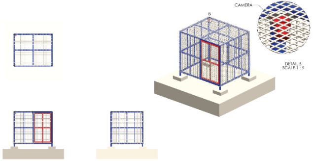
The Steel Safety Cage and Fragment Containment System is designed to provide personnel protection, fragment interception, and remote visual monitoring during the static firing of 50-100 kN class Solid Rocket Motors (SRMs). The enclosure comprises a rigid welded frame fabricated from 89 mm OD × 4 mm wall Circular Hollow Sections (CHS) for the primary structural members and 60.3 mm OD × 3.6 mm wall CHS for secondary framing. The sidewalls and roof are enclosed with 50 mm × 50 mm welded steel mesh fabricated from 6 mm diameter high-strength steel wire, providing multidirectional containment of metallic fragments while allowing adequate ventilation and unobstructed exhaust gas dispersion.
Murphy et al (2023) specify that static tests shall include measurements of external case and nozzle temperatures, strains, displacements, and self-induced vibration environments, with high-speed instrumentation sufficient to demonstrate compliance with pressure oscillation and thrust oscillation limits
| [12] | Murphy, J. J.; Tuck-Lee, J. P.; Tovar, J. M.; Stubblebine, M. J.; Goyal, V. K. Evaluation and Test Requirements for Solid Rocket Motors. 2023. |
[12]
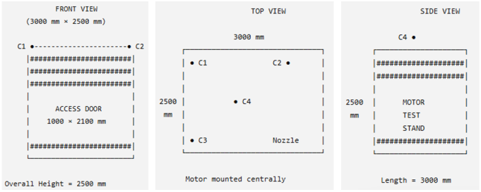
. The enclosure has overall dimensions of 3000 mm (Length) × 2500 mm (Width) × 2500 mm (Height) and is anchored to reinforced concrete foundations using M20 Grade 8.8 anchor bolts embedded in 600 mm × 600 mm × 800 mm concrete footings. A 1000 mm × 2100 mm outward-opening access door is incorporated into the front face and fitted with industrial-grade hinges, locking hardware, and emergency-release provisions. To facilitate remote observation and post-test diagnostics, the safety cage incorporates a four-camera high-definition monitoring system strategically mounted to provide complete visual coverage of the motor, ignition sequence, and exhaust region. Each camera is a 4K Ultra HD night-vision industrial IP camera (minimum resolution 3840 × 2160 pixels) equipped with infrared (IR) illumination for low-light operation, a wide dynamic range (WDR) imaging sensor, and a minimum 120° field of view. The cameras support wireless Gigabit Wi-Fi transmission (IEEE 802.11ax/Wi-Fi 6) with optional Ethernet backup for increased reliability.
Figure 2. The Steel Safety Cage and Fragment Containment System with 4×4K Night Vision Camera.
Figure 3. The Camera Positioning on the Steel Safety Cage and Fragment Containment System.
Table 1. Camera positioning on the Static Test Site.
Camera | Position | Coverage |
C1 | Front-left upper corner | Igniter, instrumentation, forward casing |
C2 | Front-right upper corner | Motor body, nozzle alignment |
C3 | Rear-left upper corner | Nozzle exit, exhaust plume, support frame |
C4 | Roof centre | Complete overhead view of the motor and test stand |
Table 2. Overall Design Summary of The Steel Safety Cage and Fragment Containment System.
Item | Specification |
Overall cage size | 3000 × 2500 × 2500 mm |
Main frame | 89 mm OD × 4 mm CHS (S355 steel) |
Secondary frame | 60.3 mm OD × 3.6 mm CHS |
Mesh | 50 × 50 × 6 mm welded steel mesh |
Door | 1000 × 2100 mm |
Foundation | 600 × 600 × 800 mm reinforced concrete footings |
Anchor bolts | M20 Grade 8.8 |
Cameras | 4 × 4K Ultra HD IP67 IR night-vision cameras |
Video transmission | Wi-Fi 6 (IEEE 802.11ax) with Ethernet backup |
Storage | 16 TB RAID NVR (30-45 days continuous recording at 4K) |
Control room distance | ≥100 m from test stand (recommended) |
The camera locations are as follows:
Camera C1 (Front-Left Corner): Mounted at the upper left front corner to monitor the ignition system, forward motor section, instrumentation, and access door.
Camera C2 (Front-Right Corner): Mounted diagonally opposite C1 to provide stereoscopic coverage of the motor casing and nozzle alignment.
Camera C3 (Rear-Left Corner): Positioned to observe the nozzle exit, plume development, and rear structural members.
Camera C4 (Roof Centre): Suspended beneath the roof frame to provide a vertical overhead view of the motor, thrust frame, and instrumentation layout.
The four cameras transmit synchronised video streams to a remote-control room located outside the designated safety exclusion zone. Video is recorded continuously on a Network Video Recorder (NVR) equipped with 16 TB RAID-configured storage, providing approximately 30-45 days of continuous 4K recording at 30 fps using H.265 compression. The monitoring system also supports real-time streaming, event-triggered recording, and timestamp synchronisation with the test data acquisition system to facilitate comprehensive post-test analysis. All camera enclosures comply with IP67 environmental protection, ensuring reliable operation under dust, moisture, vibration, and elevated acoustic conditions typical of rocket motor static firing. The cameras are mounted on vibration-isolated brackets to minimise image distortion during ignition and steady-state burn while maintaining structural integrity throughout repeated test campaigns. Although the steel safety cage provides effective protection against low- and medium-energy fragments, it is not intended to function as the primary blast containment structure during catastrophic motor failure. Consequently, the enclosure is operated in conjunction with remote firing systems, personnel exclusion zones, emergency shutdown procedures, and redundant instrumentation in accordance with established aerospace static test safety standards.
2.3.4. Calibration System
To ensure measurement accuracy and traceability, the test stand incorporates a dedicated calibration arrangement that applies known axial compression loads directly to the load-cell assembly. Calibration is performed using a hydraulic loading system or certified dead-weight apparatus capable of generating forces over the full operational range of the measurement system. The calibration fixture attaches directly to the motor mounting interface, thereby reproducing the actual thrust load path experienced during rocket motor testing. This approach minimises calibration uncertainty associated with load eccentricity and structural compliance.
Dobrodomov et al. (2026) achieved a total measurement error of 0.17% through metrological analysis and calibration of load cells using the stepwise loading-unloading method, demonstrating that careful calibration procedures can exceed sensor datasheet specifications
| [5] | Dobrodomov, O.; Proroka, V.; Dobrodomov, O.; Shvets, A.; Dalik, M.; Bilotserkovskyi, I. UNIVERSAL HIGH-PRECISION THRUST STAND FOR SOLID ROCKET MOTOR STATIC FIRE TESTS. J. Rocket-Space Technol. 2026, 35 (1), 8–13. https://doi.org/10.15421/452557 |
[5]
. Static calibration is conducted before each experimental campaign, while periodic verification is performed after testing to assess measurement drift and long-term stability. The calibration coefficients obtained are incorporated into the data acquisition software to ensure accurate real-time thrust measurement throughout the firing sequence.
2.4. Instrumentation and Data Acquisition System
The instrumentation and data acquisition system provides synchronised monitoring of thrust generation, ignition status, and system operation throughout the firing sequence.
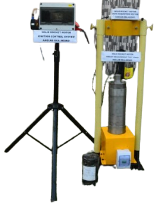
Figure 4 shows the complete measurement system consisting of the compression load cell, signal-conditioning electronics, data acquisition unit (DAQ), ignition controller, remote firing system, and a dedicated computer for real-time monitoring and data storage. The instrumentation architecture is designed to permit safe remote operation while providing continuous recording of thrust data throughout motor ignition, steady-state combustion, and burnout.
Figure 4. The Ignition system, the data acquisition system and the complete Test Stand.
2.4.1. Data Acquisition System
A dedicated Solid Rocket Motor Data Acquisition System (DAQ) is integrated with the compression load cell to record the thrust generated during static firing. The DAQ includes signal-conditioning circuitry, analogue-to-digital conversion hardware, and proprietary calibration software that converts the load cell output into real-time thrust measurements. Before each experiment, the load cell is calibrated within the software environment using the calibration constants obtained during laboratory calibration. During testing, the DAQ continuously samples the load cell output and streams the measured thrust to a connected computer through a 100 m shielded communication cable. The long cable allows the computer and operating personnel to remain outside the immediate test area while maintaining reliable real-time communication with the test stand. The acquired data are displayed live on the monitoring computer and simultaneously stored for subsequent processing, including determination of peak thrust, total impulse, thrust-time history, burn duration, and motor performance parameters.
Jayaram (2022) emphasised that data acquisition systems are indispensable in rocket engine design, allowing measurement of thrust, chamber pressure, tank pressure, mass flow, and casing temperature, whilst also providing a safety aspect by enabling remote observation of engine status
| [13] | Jayaram, S.; Pritzlaff, H.; Stack, A. Data Acquisition for Collegiate Hybrid and Solid Rocketry - An Undergraduate Research Experience; 2022. |
[13]
. Netzel et al. (2025) further demonstrated that modular DAQ architectures interfacing with load cells and pressure transducers can achieve reliable measurement for small rocket systems while prioritising cost-effectiveness
| [9] | Netzel, N. A.; Batista, D. S.; Granziera Jr., F.; Tosin, M. C. A Versatile Low-Cost Data Acquisition System for Small Rocket Engine Test Bench. HardwareX 2025, 23, e00686.
https://doi.org/10.1016/j.ohx.2025.e00686 |
[9]
.
2.4.2. Remote Ignition and Control System
Motor ignition is performed using a purpose-built Solid Rocket Motor Ignition Control System specifically developed to permit safe remote operation of the static test stand. As shown in
Figure 3, the ignition controller is connected to the test stand through a 100 m ignition cable, which carries the firing signal and system status between the control unit and the igniter circuit. The ignition controller is equipped with a wireless remote-control module that allows the operator to initiate or terminate the firing sequence from a safe operating distance of up to 400 m, corresponding to the designated safety exclusion zone. This remote capability significantly reduces personnel exposure to potential hazards associated with ignition failure, nozzle rupture, or motor overpressure.
To improve operational safety, the ignition controller incorporates an automatic 30-second countdown sequence before energising the igniter. During this countdown, a high-intensity audible alarm is activated to warn all personnel that ignition is imminent and to confirm that the test area has been evacuated. After the countdown, the controller automatically delivers the ignition current to the igniter unless the sequence is interrupted. An emergency abort function is integrated into the remote-control system, allowing the operator to immediately cancel the ignition sequence at any time before ignition if unsafe operating conditions are detected. This feature provides an additional layer of protection during pre-firing operations.
Verma (2022) described a comparable approach employing Arduino-controlled remote ignition with a 10-second warning period and LED indicators, demonstrating the feasibility of low-cost programmable ignition systems for academic rocketry applications
. UK-Rocketman (2008) similarly emphasised the importance of remote monitoring through high-resolution CCD cameras and safe firing controller circuits for static test operations
.
2.4.3. Instrumentation Integration
The ignition controller, data acquisition system, and thrust measurement assembly operate as an integrated measurement and control platform. Once the firing command is initiated, the DAQ begins continuous recording of the load-cell output while the ignition controller executes the countdown and firing sequence. The synchronised operation of both systems ensures that thrust measurements are captured from the onset of ignition through motor burnout without data loss. Following completion of the test, the recorded thrust data are archived and exported for detailed performance analysis, including calculation of peak thrust, average thrust, burn time, total impulse, and specific impulse.
2.5. Safety and Operational Systems
2.5.1. Remote Safety Operation
The static firing system is designed to eliminate the need for personnel within the immediate vicinity of the rocket motor during ignition and combustion. All firing operations are conducted from a remote safety zone located approximately 400 m from the test stand using the wireless ignition controller. The 100 m instrumentation and ignition cables provide reliable communication between the test stand and the data acquisition system, while the wireless remote enables full operational control from the designated safe area.
2.5.2. Operational Safety Features
Several engineering safety measures are incorporated into the test facility to minimise operational risks during static firing. These include:
1) A programmable 30-second ignition countdown.
2) A high-intensity audible warning alarm throughout the countdown.
3) Wireless remote firing capability up to 400 m.
4) Emergency mission abort before ignition.
5) Continuous real-time thrust monitoring.
6) Automatic recording of all thrust data.
7) Integration with the Steel Safety Cage, Fragment Containment and Remote Monitoring System described in Section 2.3.3.
8) Operation within a designated personnel exclusion zone.
2.6. Operational Procedures
2.6.1. Pre-Test Preparation
Before each static firing experiment, a comprehensive pre-test inspection is conducted to ensure the structural integrity, instrumentation readiness, and operational safety of the test facility. The following procedures are performed sequentially.
1) Test Stand Installation
The mobile test stand is transported to the designated static firing site and positioned within the reinforced steel safety cage described in Section 2.2.3. The base plate is securely anchored to the concrete foundation using high-strength anchor bolts to prevent movement during motor firing. The vertical alignment of the support columns and motor mounting assembly is verified to ensure that the motor centreline coincides with the load-cell axis.
2) Solid Rocket Motor Installation
The solid rocket motor (SRM) is carefully positioned within the adjustable split-clamp mounting assembly and securely fastened using high-strength bolts. The motor is aligned concentrically with the compression load cell to eliminate eccentric loading and ensure accurate axial thrust measurement. The nozzle is oriented vertically upward to permit unrestricted exhaust discharge.
3) Instrumentation and Electrical Connections
The compression load cell is connected to the Solid Rocket Motor Data Acquisition System (DAQ) through a 100 m shielded instrumentation cable. The ignition circuit is connected to the custom-built ignition control unit using a dedicated 100 m ignition cable, while all electrical connections are inspected for continuity, insulation integrity, and secure termination.
4) Load Cell Calibration
Before firing, the compression load cell is calibrated using certified reference loads. The resulting calibration constants are entered into the DAQ software, after which the load cell is zeroed and verified to ensure accurate thrust measurement throughout the experiment.
5) System Functional Verification
Functional checks are performed on the ignition controller, DAQ software, audible warning system, wireless remote-control module, emergency abort function, and communication links. The four wireless 4K night-vision cameras mounted on the safety cage are also activated to verify complete visual coverage of the test stand.
6) Safety Clearance
Upon completion of all system checks, personnel evacuate the test area and proceed to the designated remote operating station located approximately 400 m from the test stand. Final authorisation to commence the firing sequence is granted only after confirming that the safety exclusion zone is completely clear.
2.6.2. Static Firing Procedure
The static firing sequence is executed remotely using the developed ignition control system to eliminate personnel exposure during motor ignition and combustion.
1) System Initialization
The data acquisition software is activated and begins continuous recording of the load-cell output. Simultaneously, the wireless video monitoring system commences synchronised recording from all four cameras.
2) Automated Countdown
Following operator authorisation, the ignition controller initiates an automatic 30-second countdown sequence. Throughout the countdown, a high-intensity audible alarm continuously warns all personnel that motor ignition is imminent.
3) Remote Ignition
After the countdown, the ignition controller energises the electric igniter through the ignition cable, initiating combustion of the solid propellant. During the countdown period, the operator retains the ability to activate the emergency abort function should any unsafe condition be observed.
4) Static Firing
During combustion, the thrust generated by the motor is transmitted directly to the compression load cell. The DAQ continuously records the instantaneous thrust throughout ignition, steady-state burning, and burnout while displaying the measured thrust in real time on the monitoring computer.
5) Post-Burn Recording
Data acquisition continues for approximately 30 seconds after motor burnout to capture any residual structural vibration and confirm stabilisation of the load-cell output.
6) Post-Test Inspection
Following confirmation that combustion has ceased and the motor has cooled to a safe handling temperature, personnel re-enter the test area. The spent motor is removed from the mounting assembly and visually inspected for nozzle erosion, casing deformation, insulation integrity, and combustion characteristics.
2.6.3. Data Processing and Performance Evaluation
The thrust data recorded during each firing is exported from the data acquisition software for detailed post-processing using MATLAB. The raw load-cell signals are first corrected using the calibration coefficients obtained during the pre-test calibration procedure. Baseline drift and electrical noise are removed using an appropriate low-pass digital filter before computation of the principal performance parameters.
The following performance quantities are subsequently determined:
1) Instantaneous Thrust:
Is obtained directly from the calibrated load-cell output.
2) Peak Thrust:
Equation (
1) represents the maximum thrust generated during combustion.
Burn Time: The effective burn duration is determined from the ignition instant to complete thrust decay.
3) Total Impulse:
where Is the total burn time.
4) Average Thrust:
5) Specific Impulse:
where is the propellant mass and is the standard gravitational acceleration.
The processed thrust curves are compared with theoretical predictions obtained from ballistic performance calculations and internal ballistics models to evaluate motor performance and combustion efficiency.
3. Results
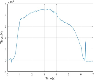
Figure 5. Thrust-Time Measurement of AAELSRM2.
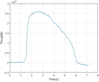
Figure 6. Thrust-Time Measurement of AAELSRM3.
The developed mobile static firing facility was experimentally validated through two independent static firing tests of indigenous solid rocket motors. During each experiment, the thrust generated by the motor was measured using the calibrated compression load cell integrated with the developed data acquisition system. The raw voltage signals acquired by the DAQ were exported to Microsoft Excel and subsequently processed in MATLAB, where calibration factors were applied to convert the measured voltages into thrust values expressed in Newtons. Appropriate signal conditioning and filtering were also performed to remove electrical noise while preserving the transient characteristics of the combustion process.
Figures 5 and 6 present the processed thrust-time histories obtained from the two firing tests.
Experiment 1
The thrust profile shown in
Figure 5 exhibits the characteristic behaviour expected from a successful solid rocket motor static firing.
Immediately after ignition, a short ignition transient is observed during the first 0.7-0.8 s, during which the thrust gradually increases as the propellant ignition spreads across the exposed burning surface. Following complete ignition, the motor rapidly reaches steady combustion, producing a sharp rise in thrust to approximately 36-38 kN within approximately one second.
After the initial pressure build-up, the motor continues to generate increasing thrust, reaching a peak value of approximately 45-46 kN at approximately 3.2-3.4 s. This gradual increase indicates progressive stabilisation of chamber pressure and efficient combustion of the propellant grain.
Following the peak thrust, the thrust decreases gradually until burnout, indicating a reduction in chamber pressure associated with propellant depletion and increasing nozzle expansion effects. The gradual nature of this decay suggests stable combustion without evidence of catastrophic combustion instability or pressure oscillation.
Near the end of combustion, a brief positive spike is observed at approximately 6.3 s. Since the signal was obtained directly from the raw DAQ output, this transient is likely attributable to one or more of the following:
1) structural vibration following burnout,
2) sudden release of residual chamber gases,
3) mechanical rebound within the load-cell assembly,
4) Electrical transient generated during ignition circuit shutdown.
Because the spike occurs after the principal combustion event and does not alter the overall thrust history, it is not considered representative of motor performance. The total burn duration was approximately 6.2-6.4 s, demonstrating sustained thrust production throughout the combustion process.
Experiment 2
The second firing test shown in
Figure 6 follows a similar combustion sequence but exhibits a lower thrust magnitude. Following ignition, thrust rises rapidly after approximately 1.4 s, reaching approximately 24-25 kN before gradually increasing to a peak thrust of approximately 26 kN around 2.5-2.8 s.
Unlike the first experiment, the thrust decay is smoother and more nearly linear, indicating relatively uniform regression of the propellant grain throughout most of the combustion period. No significant oscillatory behaviour is observed during the main burn, demonstrating stable combustion and good repeatability of the measurement system.
Combustion terminates at approximately 6.0 s, after which the measured thrust rapidly approaches zero with only minor residual oscillations caused by structural vibration and measurement noise.
Compared with Experiment 1, the second firing exhibits:
1) Lower peak thrust,
2) Slightly shorter effective burn duration,
3) Smoother thrust decay,
4) Reduced post-burn vibration.
These differences are expected because solid rocket motor performance is influenced by several factors, including:
1) Propellant grain geometry.
2) Propellant density variations.
3) Nozzle throat dimensions.
4) Ignition characteristics.
5) Manufacturing tolerances.
6) Combustion pressure development.
4. Discussion
4.1. Comparison of Static Firing Performance
Although both tests demonstrate successful motor operation, clear differences are observed in the measured thrust histories.
Experiment 1 produced a substantially higher peak thrust (approximately 45.5 kN) compared with approximately 26 kN for Experiment 2. The higher thrust level suggests that the first motor possessed a larger effective burning surface area, operated at higher chamber pressure, and employed a more energetic propellant formulation.
The burn durations of both motors are similar (approximately 6s), indicating comparable propellant masses and overall combustion times. However, the larger area beneath the thrust curve in Experiment 1 indicates a significantly greater total impulse.
The smooth rise and decay observed in both tests demonstrate that the developed test stand successfully captured the complete combustion event without signal interruption. Furthermore, the absence of significant oscillations during steady burning suggests that both the mechanical structure and data acquisition system possess sufficient rigidity and measurement stability for static firing experiments.
4.2. Validation of the Developed Test Stand
The experimental results demonstrate the successful operation of the developed mobile static firing facility.
Table 3. Shows the validation of the two experiments.
Parameter | Experiment 1 | Experiment 2 |
Peak thrust (kN) | 45.5 | 26.0 |
Time to peak thrust (s) | 3.3 | 2.6 |
Average Thrust (kN) | 27.911 | 12.342 |
Maximum Thrust (kN) | 45.5 | 26.0 |
Total Impulse (kNs) | 142.9 | 63.191 |
Specific Impulse Isp (kNs) | 1.9215 | 0.850 |
Ignition delay (s) | 0.8 | 1.4 |
Burn duration (s) | 6.3 | 6.0 |
Thrust profile | Progressive rise followed by gradual decay | Rapid rise followed by smooth decay |
Combustion stability | Stable | Stable |
Post-burn transient | Small vibration spike | Negligible |
Throughout both experiments:
The compression load cell accurately recorded the complete thrust history;
The data acquisition system continuously acquired real-time thrust data without interruption;
The MATLAB processing workflow successfully converted raw sensor outputs into calibrated thrust-time histories;
The developed remote ignition system provided synchronised firing and data acquisition;
The structural frame maintained adequate rigidity, as evidenced by the smooth thrust traces and limited structural vibration during combustion.
The only noticeable dynamic disturbance occurred immediately after burnout in Experiment 1, where a short-duration transient spike was observed. Such behaviour is commonly associated with sudden unloading of the structural system following termination of combustion and does not indicate failure of either the measurement system or the rocket motor.
Overall, the experimental results confirm that the developed test stand provides reliable measurement of thrust histories for medium-capacity solid rocket motors while simultaneously providing a safe and practical platform for propulsion research.
4.3. Limitations
Although the developed mobile static firing facility successfully achieved its primary design objectives and demonstrated reliable performance during experimental validation, several limitations remain that provide opportunities for future enhancement.
The present configuration employs a centrally mounted compression load cell designed to measure the axial thrust component generated by the solid rocket motor. Consequently, transverse loads, bending moments, and thrust-vector deviations cannot presently be quantified. Dobrodomov et al. (2026) addressed this limitation by developing a three-axis load cell scheme capable of determining thrust magnitude and spatial characteristics of the thrust vector, including deflection angle and coordinates of the point of application
| [5] | Dobrodomov, O.; Proroka, V.; Dobrodomov, O.; Shvets, A.; Dalik, M.; Bilotserkovskyi, I. UNIVERSAL HIGH-PRECISION THRUST STAND FOR SOLID ROCKET MOTOR STATIC FIRE TESTS. J. Rocket-Space Technol. 2026, 35 (1), 8–13. https://doi.org/10.15421/452557 |
[5]
. Whilst this arrangement is adequate for conventional fixed-nozzle static firing tests, future investigations involving thrust-vector control or nozzle misalignment would require the incorporation of a multi-axis force measurement system.
Furthermore, the current instrumentation architecture primarily focuses on thrust measurement as the principal performance parameter. Although thrust remains the most important indicator of propulsion performance, a more comprehensive characterisation of motor internal ballistics would benefit from the simultaneous acquisition of combustion chamber pressure, propellant surface temperature, nozzle temperature, casing strain, and exhaust plume diagnostics. The absence of these complementary measurements limits detailed correlation between combustion behaviour and the measured thrust profile.
The manually adjustable motor clamping mechanism provides adequate flexibility for laboratory-scale solid rocket motors but becomes increasingly difficult to operate as motor dimensions and mass increase. Future testing of larger propulsion systems would therefore require the integration of a mechanical lifting device or hydraulic positioning system to improve handling efficiency and operator safety.
Although the structural frame was designed with substantial strength margins and validated through finite element analysis, repeated exposure to high-temperature exhaust gases and combustion products may gradually degrade protective coatings and localised structural components positioned near the nozzle exit. Periodic inspection and maintenance are therefore necessary to ensure long-term structural reliability.
In addition, all experiments reported in this study were conducted under ambient atmospheric conditions. Consequently, the facility cannot reproduce reduced-pressure environments representative of high-altitude or near-space operation. The measured propulsion performance therefore reflects ground static firing conditions rather than in-flight operating environments.
Finally, while the integrated wireless camera system provided effective visual monitoring of the firing sequence, the current implementation records standard video imagery only. The absence of synchronised high-speed optical diagnostics limits detailed investigation of transient combustion phenomena, nozzle flow development, ignition dynamics, and plume instability.
4.4. Future Developments
The encouraging performance of the developed test facility provides a strong foundation for the development of a more advanced indigenous propulsion testing platform capable of supporting future launch vehicle and aerospace propulsion research within Nigeria.
Future improvements will focus on enhancing measurement capability, operational automation, structural adaptability, and intelligent diagnostic systems. Planned developments include:
1) Integration of high-frequency combustion chamber pressure transducers to enable simultaneous acquisition of chamber pressure and thrust data for comprehensive internal ballistics analysis.
2) Installation of thermocouples, infrared thermal cameras, and heat-flux sensors for continuous monitoring of motor casing temperature, nozzle thermal loading, insulation performance, and combustion chamber heat transfer.
3) Development of a fully wireless data acquisition architecture to replace long instrumentation cables while maintaining synchronised, high-speed, real-time data transmission between the test stand and remote-control station.
4) Integration of high-speed optical diagnostics, including synchronised high-speed cameras and image-processing algorithms, for visualisation of ignition transients, exhaust plume development, combustion stability, and nozzle flow behaviour.
5) Development of a six-component force measurement platform capable of simultaneously measuring axial thrust, lateral forces, pitching moments, and yawing moments for advanced propulsion system evaluation.
6) Application of artificial intelligence and machine-learning techniques for automated signal conditioning, anomaly detection, combustion stability assessment, predictive maintenance, and intelligent performance prediction from historical firing data.
7) Implementation of cloud-based remote monitoring and digital test management, enabling real-time data visualisation, automatic report generation, secure experimental data archiving, and collaborative propulsion research across multiple institutions.
8) Development of an automated motor handling and positioning system incorporating hydraulic lifting and precision alignment mechanisms to facilitate testing of larger and heavier propulsion systems.
9) Integration of altitude-simulation capability through reduced-pressure exhaust systems for investigating propulsion performance under representative near-space operating conditions.
5. Conclusions
This study presented the design, fabrication, instrumentation, structural validation, and experimental evaluation of a mobile static firing test stand developed for the performance characterisation of solid rocket motors at the Advanced Aerospace Engines Laboratory (AAEL).
The developed facility successfully integrates a structurally reinforced steel support frame, an adjustable motor mounting assembly, a calibrated compression load cell, a dedicated thrust data acquisition system, a programmable remote ignition controller, and a reinforced steel safety cage equipped with four strategically positioned wireless 4K night-vision cameras for continuous remote monitoring during static firing operations. The remote ignition system incorporates a programmable 30-second safety countdown, high-intensity audible warning alarm, emergency mission abort capability, and wireless operation over distances of up to 400 m, thereby significantly improving operational safety while allowing complete remote execution of static firing experiments. Real-time thrust measurements are continuously acquired through the calibrated compression load cell and transmitted via a 100 m shielded instrumentation cable to the remote data acquisition computer, where the firing data are recorded and subsequently processed using MATLAB. Finite element structural analysis confirmed that the primary structural members possess sufficient strength and stiffness to safely withstand the expected loading conditions encountered during static firing operations. Experimental validation through two independent static firing tests further demonstrated the capability of the developed facility to accurately capture complete thrust-time histories, including ignition transients, peak thrust, steady combustion, burnout, and post-combustion response. The measured thrust profiles exhibited stable combustion behaviour and demonstrated the reliability of the integrated measurement and data acquisition system. This work establishes an indigenous experimental propulsion testing capability that significantly strengthens Nigeria's capacity for aerospace propulsion research. The facility provides a practical, modular, and economically sustainable platform for evaluating solid rocket motors, validating propulsion system designs, characterising propellant performance, and supporting future research in combustion diagnostics, nozzle optimisation, propulsion system development, and launch vehicle technologies.
Abbreviations
AAEL | Advanced Aerospace Engines Laboratory |
BATCSTP | Bola Ahmed Tinubu Centre for Space Transport and Propulsion |
CCD | Charge-Coupled Device |
CHS | Circular Hollow Sections |
DAQ | Data Acquisition System |
ESA | European Space Agency |
ISRO | Indian Space Research Organisation |
JAXA | Japan Aerospace Exploration Agency |
LED | Light-Emitting Diode |
MATLAB | Matrix Laboratory |
NASA | National Aeronautics and Space Administration |
NASRDA | National Space Research and Development Agency |
NVR | Network Video Recorder |
RETF | Rocket Engine Test Facility |
SRM | Solid Rocket Motor |
STS | Static Test Stand |
WDR | Wide Dynamic Range |
Acknowledgments
We sincerely appreciate and acknowledge the efforts and contributions of the members of staff of the Advanced Aerospace Engines Laboratory, Oka-Akoko, Ondo State, Nigeria. We also appreciate Dr Gbadebo Omoniyi Adeniyi, Dr Durojaye Rasheed Olalekan, and Dr Adetoro Lanre Moshood for their mentorship towards the actualisation of this project.
Author Contributions
Emmanuel Unekuojo Enejor: Conceptualization, Formal Analysis, Investigation, Validation, Writing – original draft, Writing – review & editing
Nelson Oluwole Ibigbami: Conceptualization, Methodology, Project administration, Resources, Supervision
Babatunde Ameen Gbajabiamila: Formal Analysis, Investigation, Software, Visualization
Moses Ugbedeojo Negedu: Methodology, Resources, Software, Supervision, Visualization
Olawale Babasola Adebanjo: Investigation, Supervision, Visualization.
Ismail Olusegun Lawal: Project administration, Formal Analysis, Investigation, Supervision
Bamisaye Ayodeji Peter: Data curation, Formal Analysis, Investigation, Software, Visualization
Conflicts of Interest
The authors declare no conflicts of interest.
References
| [1] |
Krows, A.; Wooten, J.; Smith, A.; Halley, D.; Shavezipur, D. K. Design And Simulation of a Static Fire Test Stand for Solid Rocket Motor Testing. In 2025 Regional Student Conferences; American Institute of Aeronautics and Astronautics, 2025.
https://doi.org/10.2514/6.2025-99377
|
| [2] |
Fernandes, F. A. C.; Souto, C. d’Andrade; Pirk, R. Static Firing Tests of Solid Propellant Rocket Motors: Uncertainty Levels of Thrust Measurements. J. Aerosp. Technol. Manag. 2022, 14, e2022.
https://doi.org/10.1590/jatm.v14.1270
|
| [3] |
Freeman, C. Solid Rocket Motor Static Fire Test Stand Optimization : Load Cell Effects and Other Uncertainties, 2018.
https://louis.uah.edu/uah-theses/263
|
| [4] |
Migliorino, M. T.; Aiello, M.; Berti, M.; Rotondi, M.; D’Alessandro, S.; Bianchi, D.; Jahjah, M.; Pizzarelli, M. Student Firing Tests and Launches with Commercial and Self-Made Solid Rocket Motors. Acta Astronaut. 2022, 197, 23–34.
https://doi.org/10.1016/j.actaastro.2022.04.025
|
| [5] |
Dobrodomov, O.; Proroka, V.; Dobrodomov, O.; Shvets, A.; Dalik, M.; Bilotserkovskyi, I. UNIVERSAL HIGH-PRECISION THRUST STAND FOR SOLID ROCKET MOTOR STATIC FIRE TESTS. J. Rocket-Space Technol. 2026, 35 (1), 8–13.
https://doi.org/10.15421/452557
|
| [6] |
Miao, Y.; Wang, G.; Rui, X.; Tu, T. Study on Test Dynamics Method of Non-Full Loading Firing for Multiple Launch Rocket System. Mech. Syst. Signal Process. 2019, 122, 463–479.
https://doi.org/10.1016/j.ymssp.2018.12.043
|
| [7] |
Nakka, R. Richard Nakka’s Experimental Rocketry Site. Richard Nakka’s Experimental Rocketry Web Site.
https://www.nakka-rocketry.net/static.html
(accessed 2026-07-14).
|
| [8] |
NASA. Rocket Engine Test Facility - Origins of the RETF - NASA.
https://www.nasa.gov/rocket-engine-test-facility-origins-of-the-retf/
(accessed 2026-07-14).
|
| [9] |
Netzel, N. A.; Batista, D. S.; Granziera Jr., F.; Tosin, M. C. A Versatile Low-Cost Data Acquisition System for Small Rocket Engine Test Bench. HardwareX 2025, 23, e00686.
https://doi.org/10.1016/j.ohx.2025.e00686
|
| [10] |
Study on Test Dynamics Method of Non-Full Loading Firing for Multiple Launch Rocket System. Mech. Syst. Signal Process. 2019, 122, 463–479.
https://doi.org/10.1016/j.ymssp.2018.12.043
|
| [11] |
Prodan, M. Design of test benches for cryogenic hybrid rocket engines. laurea, Politecnico di Torino, 2025.
https://webthesis.biblio.polito.it/37495/
(accessed 2026-07-30).
|
| [12] |
Murphy, J. J.; Tuck-Lee, J. P.; Tovar, J. M.; Stubblebine, M. J.; Goyal, V. K. Evaluation and Test Requirements for Solid Rocket Motors. 2023.
|
| [13] |
Jayaram, S.; Pritzlaff, H.; Stack, A. Data Acquisition for Collegiate Hybrid and Solid Rocketry - An Undergraduate Research Experience; 2022.
|
| [14] |
James, M. Computer Vision of Analog Gauges as an Alternative to Digital Flight Test Instrumentation. Theses Diss. 2022.
|
| [15] |
Montoro, Á. T.; Robles, L. J. M.; Gallardo, A. P. Rocket Engine Static Fire Data Acquisition. Data Acquisition | Test and Measurement Solutions.
https://dewesoft.com/blog/rocket-engine-static-fire-test
(accessed 2026-07-14).
|
| [16] |
Verma, P. H. Static Test Pad for Rocket Motor; Internship Report; Space Technology and Aeronautical Rocketry: Department Of Aeronautics, Hindustan Institute Of Technological Sciences, 2022.
https://hindustanuniv.ac.in/assets/naac/CA/1_3_4/336_Hemanth_Verma_Pinnamaraju.pdf
|
| [17] |
UKRocketman. Static Test Stand for Rocket Motors -
http://www.ukrocketman.com/rocketry/statictest.shtml
(accessed 2026-07-14).
|
Cite This Article
-
APA Style
Enejor, E. U., Ibigbami, N. O., Gbajabiamila, B. A., Negedu, M. U., Adebanjo, O. B., et al. (2026). Design, Development, and Structural Validation of a Mobile Static Test Stand for Solid Rocket Motor Performance Evaluation. American Journal of Science, Engineering and Technology, 11(3), 159-172. https://doi.org/10.11648/j.ajset.20261103.16
 Copy
|
Copy
|
 Download
ACS Style
Enejor, E. U.; Ibigbami, N. O.; Gbajabiamila, B. A.; Negedu, M. U.; Adebanjo, O. B., et al. Design, Development, and Structural Validation of a Mobile Static Test Stand for Solid Rocket Motor Performance Evaluation. Am. J. Sci. Eng. Technol. 2026, 11(3), 159-172. doi: 10.11648/j.ajset.20261103.16
Copy
|
Download
AMA Style
Enejor EU, Ibigbami NO, Gbajabiamila BA, Negedu MU, Adebanjo OB, et al. Design, Development, and Structural Validation of a Mobile Static Test Stand for Solid Rocket Motor Performance Evaluation. Am J Sci Eng Technol. 2026;11(3):159-172. doi: 10.11648/j.ajset.20261103.16
Copy
|
Download
-
@article{10.11648/j.ajset.20261103.16,
  author = {Emmanuel Unekuojo Enejor and Nelson Oluwole Ibigbami and Babatunde Ameen Gbajabiamila and Moses Ugbedeojo Negedu and Olawale Babasola Adebanjo and Ismail Olusegun Lawal and Bamisaye Ayodeji Peter},
  title = {Design, Development, and Structural Validation of a Mobile Static Test Stand for Solid Rocket Motor Performance Evaluation},
  journal = {American Journal of Science, Engineering and Technology},
  volume = {11},
  number = {3},
  pages = {159-172},
  doi = {10.11648/j.ajset.20261103.16},
  url = {https://doi.org/10.11648/j.ajset.20261103.16},
  eprint = {https://article.sciencepublishinggroup.com/pdf/10.11648.j.ajset.20261103.16},
  abstract = {Reliable static firing facilities are indispensable for evaluating the performance, structural integrity, and operational safety of solid rocket motors (SRMs). However, the high cost and limited availability of dedicated propulsion test facilities continue to constrain experimental rocket propulsion research in many developing countries. This study presents the design, fabrication, and structural validation of a cost-effective mobile static test stand developed at the Advanced Aerospace Engines Laboratory (AAEL) in Nigeria to support indigenous solid rocket motor research and development. The developed facility integrates a rigid steel support structure, an adjustable motor mounting assembly, a centrally mounted compression load cell, a dedicated thrust data acquisition system, a programmable remote ignition controller, and a reinforced steel safety cage equipped with wireless 4K night-vision cameras for real-time remote monitoring. The ignition system incorporates a programmable 30-second countdown sequence, an audible warning alarm, wireless remote firing capability over distances up to 400 m, and an emergency abort function to enhance operational safety. The structural components of the test stand were designed using conventional mechanical design principles and validated through finite element analysis to ensure adequate stiffness and structural integrity under the maximum expected loading conditions. Real-time thrust measurements are obtained through a calibrated compression load cell integrated with a dedicated data acquisition system capable of continuously recording thrust throughout the combustion process. The developed test facility provides a practical, reliable, and economically sustainable platform for the experimental evaluation of solid rocket motors developed within Nigeria's indigenous space programme.},
 year = {2026}
}
Copy
|
Download
-
TY  - JOUR
T1  - Design, Development, and Structural Validation of a Mobile Static Test Stand for Solid Rocket Motor Performance Evaluation
AU  - Emmanuel Unekuojo Enejor
AU  - Nelson Oluwole Ibigbami
AU  - Babatunde Ameen Gbajabiamila
AU  - Moses Ugbedeojo Negedu
AU  - Olawale Babasola Adebanjo
AU  - Ismail Olusegun Lawal
AU  - Bamisaye Ayodeji Peter
Y1  - 2026/08/20
PY  - 2026
N1  - https://doi.org/10.11648/j.ajset.20261103.16
DO  - 10.11648/j.ajset.20261103.16
T2  - American Journal of Science, Engineering and Technology
JF  - American Journal of Science, Engineering and Technology
JO  - American Journal of Science, Engineering and Technology
SP  - 159
EP  - 172
PB  - Science Publishing Group
SN  - 2578-8353
UR  - https://doi.org/10.11648/j.ajset.20261103.16
AB  - Reliable static firing facilities are indispensable for evaluating the performance, structural integrity, and operational safety of solid rocket motors (SRMs). However, the high cost and limited availability of dedicated propulsion test facilities continue to constrain experimental rocket propulsion research in many developing countries. This study presents the design, fabrication, and structural validation of a cost-effective mobile static test stand developed at the Advanced Aerospace Engines Laboratory (AAEL) in Nigeria to support indigenous solid rocket motor research and development. The developed facility integrates a rigid steel support structure, an adjustable motor mounting assembly, a centrally mounted compression load cell, a dedicated thrust data acquisition system, a programmable remote ignition controller, and a reinforced steel safety cage equipped with wireless 4K night-vision cameras for real-time remote monitoring. The ignition system incorporates a programmable 30-second countdown sequence, an audible warning alarm, wireless remote firing capability over distances up to 400 m, and an emergency abort function to enhance operational safety. The structural components of the test stand were designed using conventional mechanical design principles and validated through finite element analysis to ensure adequate stiffness and structural integrity under the maximum expected loading conditions. Real-time thrust measurements are obtained through a calibrated compression load cell integrated with a dedicated data acquisition system capable of continuously recording thrust throughout the combustion process. The developed test facility provides a practical, reliable, and economically sustainable platform for the experimental evaluation of solid rocket motors developed within Nigeria's indigenous space programme.
VL  - 11
IS  - 3
ER  -
Copy
|
Download

 ,
Nelson Oluwole Ibigbami,
Babatunde Ameen Gbajabiamila,
Moses Ugbedeojo Negedu,
Olawale Babasola Adebanjo
,
Nelson Oluwole Ibigbami,
Babatunde Ameen Gbajabiamila,
Moses Ugbedeojo Negedu,
Olawale Babasola Adebanjo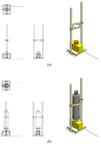



 Share This Article
 Twitter
 Linked In
 Facebook